![]()
This is the second edition of the Transport Canada Helicopter Flight Training Manual. The Manual has been prepared for the use of student pilots learning to fly, pilots improving their qualifications, and flight instructors in the conduct of instruction for student pilots. It provides information and direction in the introduction and performance of flight training manoeuvres as well as basic information related to flight training courses.
In preparing this manual, the objective was to provide progressive study material using basic terms and language aligned to pilot training at the elementary level. A working knowledge of the information contained in this manual will enable the student to receive maximum benefit from the air exercises.
It should be pointed out that the air exercises have been addressed in a logical suggested progression, but they can be adjusted to conform to any school’s syllabus.
The first exercise will not normally involve any detailed training, but will consist of a flight during which your role as student will be mainly that of observer, even though you will occupy the seat from which you will subsequently fly. This flight will begin to accustom you to the sensation of flying, and to the appearance of the country from the air. However, it is the flight instructor’s prerogative to take a more positive approach to instruction at this time, and may also include some part of Exercise 3: “Effects of Controls”.
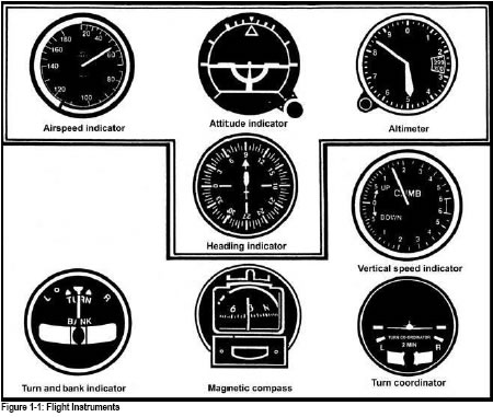
In preparation for this flight your instructor will first accustom you to the cockpit layout, including the flight and engine instruments (Fig 1-1 and 1-2). The arrangement shown is the most common but you may well find that the helicopter you are flying is slightly different.
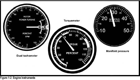
There are several gauges that are vital to the operation of the engine that will be covered in detail by your instructor. All of these gauges indicate the temperatures and pressures (T’s and P’s) of the engine at any given time. There is a common method of marking the instruments with colour coding, but you should memorize the limitations for the helicopter you are flying. Refer to the helicopter flight manual for the limitations during any phase of engine operation.
The first flight will be an entirely new experience, but what may look complicated and difficult at this time will become less and less so as your flight training progresses.
You will be asked to keep your hands lightly on the cyclic stick and collective lever, and your feet lightly on the tail rotor pedals. The instructor will emphasise that only small, smooth movements are required to control the helicopter, and will briefly discuss procedures to be followed in future flight training exercises.
There will be a temptation for anyone who has never flown before to lean away from the bank as the aircraft turns. Resist this temptation as strongly as possible and attempt to become “one with the helicopter”.
The instructor will point out readily identifiable local landmarks and explain their orientation to the heliport/airport. The function of the airspeed indicator and the altimeter will be explained, and periodically you may be asked to report the altitude and airspeed of the helicopter. The function of other instruments may also be explained.
Your instructor will explain the need for a positive handover and takeover of the flight controls. The person flying the helicopter will ensure that the other is on the controls before saying “You have control”; the person assuming control will then respond “I have control” and fly the helicopter.
The need for a constant and thorough lookout for other aircraft will be described, together with the clock method of reporting aircraft to the other crewmember. Do not hesitate to ask questions. The instructor’s voice must be completely audible and clearly understandable; if it is not, tell him so.
This exercise does not normally involve a flight, but will acquaint you with the preparations necessary before commencing a flight. Proper pre-flight preparation plays a fundamental part in flight safety, and will reduce the possibility of accidents, or incidents.
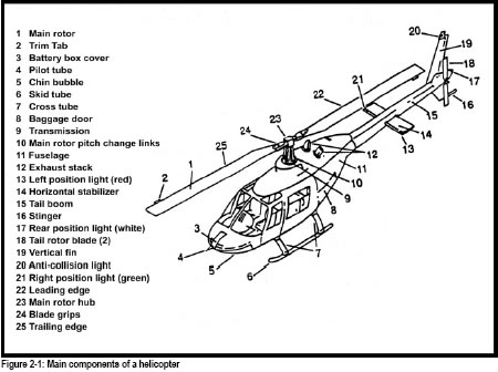
The main components of the helicopter will be pointed out to you, and your instructor will subsequently provide a detailed explanation of each part (Fig 2-1).
You may consider the sequence of events leading up to the takeoff as falling into three phases:
During your initial stages of training, your instructor will include the flight planning stage in your pre-flight briefings, but as the course progresses you will participate more fully in this aspect of preparation for flight. This will include the checking of weather reports and forecasts to extract information appropriate to the intended flight and the destination. Selecting the route, the checking of NOTAMs, preparing a flight log, and the filing of a Transport Canada Flight Plan or Flight Itinerary are also components of flight planning.
Your instructor will show you all the documents, which must be on board the helicopter on every flight. It is the responsibility of the pilot-in-command to ensure that all documentation required for an aircraft and its crew is on board and/or current and valid for the proposed flight.
Logbook entries are the responsibility of the pilot-in-command who ensures they have been entered in the correct manner to record the events of the flight. Each period between a takeoff and a landing is generally considered a flight requiring a separate log entry.
Your instructor will explain exceptions to this rule, the significance of each document, and how to check each for validity.
Before any flight, the pilot-in-command of an aircraft must ensure that:
The maximum weight limitations are set by the structural capabilities of the helicopter, an allowance being made for the extra forces encountered in turbulence and extremes in control movements.
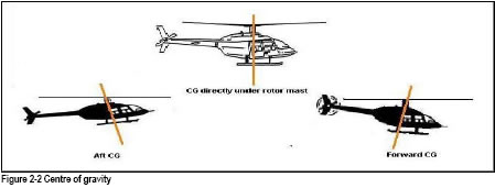
The centre of gravity is defined as a location where all of the aircraft’s weight is considered to be concentrated. Improper balance of a helicopter’s load can result in serious control problems. The centre of gravity has quite a limited range of movement. The range of movement of the cyclic control system sets this limit (Fig 2-2).
CG AFT LIMIT (TAIL-LOW)
When the CG is aft, the cyclic is in the forward position. With a tail-low attitude, you need even greater forward displacement of the cyclic while hovering into the wind. If the helicopter exceeds aft CG limits, hovering is not possible. Takeoff and landing in the strong headwind conditions may be critical, because you need greater forward cyclic to hover as well as levelling off after
a flare on an autorotation approach.
CG FORWARD LIMIT (NOSE-LOW)
When the CG is forward, the cyclic is in the aft of the neutral position. With a nose-low attitude, you need excessive rearward displacement of the cyclic control to maintain a hover in a no-wind condition. You should not continue flight in this condition, since you could rapidly run out of rearward cyclic control as you consume fuel. In the event of engine failure and the resulting autorotation, you may not have enough cyclic control to flare properly for the landing.
The cyclic will be displaced opposite to the position of the load. This is more noticeable if litters are being used. For slope operations, care must be taken and you must prevent the static/dynamic roll over situations.
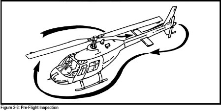
It is the responsibility of the pilot-in-command to ensure that an aircraft is safe and fit in all respects for the intended flight. The pre-flight external inspection determines, from the pilot’s point of view, that the aircraft is serviceable and that it has sufficient fuel and oil for the intended flight. Your pre-flight inspection should follow a set pattern and sequence. In this way, no items will be forgotten and your sequence will be similar no matter what type of helicopter you fly in the future. Most manufacturers recommend that you begin at the nose, on the right hand side to finish at the point you started. (Fig 2-3). Having completed the external inspection in this fashion you are ready to enter the cockpit. A recommended method of conducting this inspection is found in most helicopter flight manuals.
While walking out to the helicopter you should take note of the strength and direction of the wind, and the presence of any other aircraft, or obstacles, which may affect the starting procedures or the subsequent takeoff.
Your instructor will teach you the correct procedures for briefing your passengers at this stage.
Where possible, the helicopter should be positioned into wind, clear of any obstructions to main and tail rotor blades, with a fire extinguisher available. It is discourteous and may be hazardous to start a helicopter close to buildings or vehicles, as damage may be caused by the rotor downwash as the helicopter lifts into a hover. Light aircraft parked nearby may suffer substantial damage to their control surfaces.
Your instructor will demonstrate a pre-flight inspection and explain what you should look for to determine the airworthiness of the helicopter. If during this inspection you discover an un-serviceability, or have any doubts about the helicopter’s airworthiness, then it should not be flown. All schools have a system of reporting defects. It could well be just to inform your own instructor, but do not be afraid to express your doubts to an engineer.
Before starting the engine, a thorough cockpit and “pre-start” check utilising a checklist shall be performed. Completion of these checks using the checklist is very important, and should be conducted in accordance with the recommended procedures contained in the helicopter flight manual. This pre-flight check will ensure that components are not damaged through incorrect starting procedures. Using the appropriate checklist, all further checks, such as starting, warm-up and run-up, if applicable, should likewise be performed in accordance with the manufacturer’s recommendations.
Following the flight you must once again, using a checklist, follow the recommended procedure for engine cool down, and shutdown. Your instructor will demonstrate the correct starting and shutdown procedures during this exercise. As your course progresses you will learn to perform these procedures on your own, using the checklists that should be provided by your school.
In this exercise you will learn the range of attitudes through which the helicopter will normally be operated and how the controls are used to achieve and maintain the desired flight attitudes. The skills learned in this exercise form the basis for all future helicopter air exercises.
Now that flight training has begun in earnest, start observing this rule: look around. For safety in flight, keep alert for other aircraft. Look out continually. Realise that there are blind spots behind and beneath your helicopter, and never assume that others have seen you. Be especially alert during nose-up attitudes of the helicopter when the blind spot enlarges due to a decrease in forward visibility.
A pilot must be constantly on the lookout for other aircraft and must keep up a continuing search of the sky. It is commonly believed that the eye sees everything in its field with equal clarity. This is not so. Fix your gaze about 5 degrees to one side of this page, and you will no longer be able to read the printed material. Studies have revealed that the eye perceives very poorly when it is in motion. Wide sweeping eye excursions are almost futile and may be a hazard, since they give the impression that large areas of sky have been examined. A series of short, regularly spaced eye movements is recommended for maximum efficiency in searching the sky.
Your instructor will demonstrate the correct adjustment of the flight controls in preparation for flight, and the correct use of the control frictions. Ensure that the pedals are adjusted so that you are sitting in a comfortable position, or you may find yourself becoming fatigued very quickly.
Moving the cyclic stick will tilt the rotor disc and cause the helicopter to either pitch or roll, or a combination of the two, effecting motion in the direction the cyclic is moved. Remembering that the total lift reaction is always perpendicular to the rotor disc, when the disc is tilted from the lift (vertical) component, the thrust (horizontal) component will cause the helicopter to move in the direction of rotor tilt. (See Figure 3-1). After the helicopter has been started your instructor will demonstrate how the disc reacts to cyclic control movements. Observe that the disc tilts in a direction corresponding to the direction in which you have moved the cyclic.
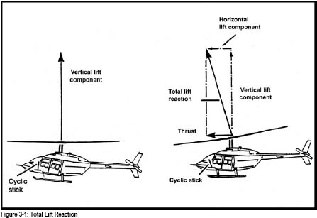
Notice that the total lift reaction is unchanged in magnitude, but the cyclic movement has changed the direction of that force, thus also affecting the attitude and airspeed of the helicopter.
Your instructor will demonstrate the effects of cyclic stick movement to maintain straight and level flight, as this is the basis for all attitude changes. To begin with, you should note the helicopter attitude by reference to the horizon, and your instructor will also point out the instrument indications in response to cyclic inputs. The cyclic stick controls the aircraft attitude and therefore the airspeed, which in turn affects altitude.
Fore and aft cyclic movement is used to achieve and maintain the desired attitude to select the airspeed. The amount and rate of attitude change varies with the amount and rate of cyclic movement. Lateral movements of the cyclic will produce and control-rolling motion to establish and maintain desired angles of bank, or to restore the helicopter to a level attitude. Once again the amount and rate of roll varies with the amount and rate of cyclic movement.
Always move the cyclic smoothly and by small amounts. Be aware that abrupt control movements can reduce the life of components, and may even damage them.
The collective lever is so named because when the collective is moved, it alters the pitch, or angle of attack, of all main rotor blades by the same amount at the same time. Raising the collective increases all main rotor blade angles of attack, resulting in an increase in the total lift. (Fig 3-2)
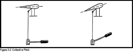
Decreasing collective will of course result in the opposite reaction. The primary effect of moving collective will be a change in height, and the secondary effect is a change in yaw.
A twist grip throttle is mounted on the forward end of the collective. It is used to set the engine and rotor RPM to the normal operating range on piston engine helicopters. Your instructor will demonstrate that in addition to increasing RPM, applying throttle will also cause the manifold pressure to increase, and the helicopter to yaw to the right. Reducing throttle, while causing a decrease in RPM and manifold pressure, will again cause yaw, this time to the left. Your instructor will also demonstrate proper coordination of throttle, and collective movements, to maintain both manifold pressures, engine and rotor RPM in the correct operating ranges.
On most light turbine helicopters, the throttle is used to bring the engine up into the governed range, where precise adjustments of the engine and rotor RPM are made through the engine governor “beep” switch. Once set correctly, RPM will remain relatively constant regardless of collective movement. It is worth mentioning that some helicopters do not have a collective mounted throttle; some have the throttle on the floor, others on a roof console.
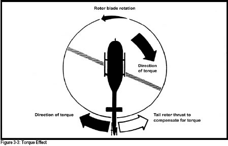
The purpose of the pedal controlled tail rotor is to counteract the torque effect of the main rotor, to control the heading of the helicopter during hovering flight, and to initiate turns while in the hover. It is not, however, used to control the heading while in cruise flight, but only to compensate for torque. This puts the helicopter in longitudinal trim so as to maintain co-ordinated flight (Figure 3-3 refers). Some helicopters have a ‘ball’ to assist you to keep in co-ordinated flight. This is a simple spirit level device, if the ball is deflected to the right, apply right pedal until the ball centres and vice versa.
Movement of the pedals will effect a change in the collective pitch of the tail rotor blades. The result of pressure on one pedal will be a yaw in the corresponding direction, i.e.; pressure on the left pedal will cause the nose to yaw left, and vice versa. An increase in pitch will require an increase in power, a decrease in pitch a decrease in power. On North American helicopters the left pedal is the “power” pedal. In other words when you apply left pedal you will require more power.
Your instructor will demonstrate to you that the need for pedal application must be anticipated every time you change power. In fact, any change in collective or cyclic position will require you to adjust the pedals in order to maintain co-ordinated flight.
These controls, while not actually used to control the helicopter in flight, are nevertheless vital to the safe and comfortable operation of the helicopter. Depending on helicopter type, ancillary controls may include: carburettor heat, mixture control, engine anti-icing, windshield defogging, rotor brake and heater. Your instructor will demonstrate the correct use of the particular ancillary controls that equip the type of helicopter on which you will be training.
CARBURETTOR HEAT CONTROL
Carburettor Icing. Under certain moist atmospheric conditions, with air temperatures ranging anywhere from -13 degrees Celsius to +38 degrees Celsius, (Fig 3-4) it is possible for ice to form in the induction system (Fig 3-5).
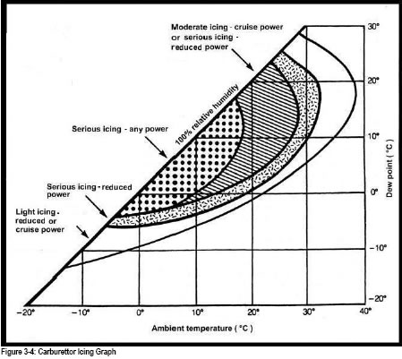
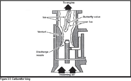
The rapid cooling in the induction system using a float type carburettor is caused by the absorption of heat from the air during vaporisation of the fuel. It is also due in part to the high expansion of air through the carburettor venturi. As a result of the latter two influences, the temperature in the venturi may drop as much as 21 degrees Celsius below the temperature of the incoming air. If this air contains a large amount of moisture, the cooling process can cause ice to form. This may build up to such an extent that a drop in power output results, and if not corrected may cause complete engine stoppage. Indications of icing to the pilot are a loss of manifold pressure together with engine roughness. To prevent the formation of carburettor ice piston engine helicopters not using fuel injection are equipped with a controllable system for preheating the air before it enters the carburettor. They are also equipped with a gauge, which aids in the prevention of carburettor ice.
Carburettor Heat.Normally you can anticipate possible icing by checking the carburettor heat gauge and use carburettor heat before the ice forms. However, should ice begin to form use the “full heat” position long enough to be sure of eliminating the ice. Using full heat will initially cause a loss of power and possible engine roughness. Heated air directed in the induction system will melt the ice, which goes through the engine as water, causing some of the roughness and more power loss. Despite this temporary roughness and attendant moderate power loss, a pilot is not damaging the engine at a cruise power setting of 75 per cent or less with any amount of heat.
When using carburettor heat, there are related factors to remember. The engine loses an average of 9 per cent of its power when heat is applied. This is due to the reduced volumetric efficiency of heated air and loss of the ram air feature. Carburettor heat also creates a richer mixture, which may cause the engine to run rough, particularly at full heat. Increase power to the former setting until the engine runs smoothly again.
Carburettor icing may be controlled, or avoided, by adopting the following practices:
There is a misconception that it does not matter, to the efficiency of the engine, whether the carburettor heat is on or off. If this were true, engine manufacturers would design their engines so that heated air was constantly directed through the carburettor air intake system to completely eradicate the problem of carburettor icing. But they don’t because the application of carburettor heat in standard atmospheric conditions will:
As the ambient temperature decreases, the effect of carburettor heat on the efficiency of the engine also decreases. Light helicopter engines, operated at extremely low (winter) ambient temperatures, may require the warming influence of carburettor heat to ensure adequate response to throttle application.
Most mixture adjustments are required during changes of altitude or during operations at high altitude. As an aircraft gains altitude, the surrounding air becomes less dense. At altitude, the engine draws a lesser weight of air into its cylinders than it does on the ground. If the weight of the fuel drawn into the cylinders remained the same, regardless of altitude, the mixture would become too rich at altitude.
To maintain the correct fuel/air mixture, you must be able to adjust the amount of fuel that is mixed with the incoming air. This is the function of the mixture control. This adjustment, often referred to as “leaning the mixture”, varies from one aircraft to another. Refer to the Approved Rotorcraft Flight Manual (RFM) to determine specific procedures for your helicopter. Note that most manufactures do not recommend leaning helicopters in flight. Generally, the accepted procedure for leaning the mixture is to move the mixture control slowly toward the “lean” position until maximum RPM is obtained with a fixed power setting. Then, move the mixture control toward “rich” until a decrease in RPM is just perceptible. This produces optimum power for the throttle setting, with a slightly rich mixture to prevent overheating, since sustained operations with the mixture too lean can damage the engine: high engine temperatures can cause excessive engine wear or even failure. The best way to avoid this type of situation is to monitor the engine temperature gauges regularly and follow the manufacturer’s guidelines for maintaining the proper mixture.
Although the windshield defogging system is not classed as an ancillary control, a phase of its operation is included in this exercise.
The windshield of a helicopter should at all times be kept clear and free of anything that will interfere with forward visibility, not only for control purposes, but also to see outside obstructions and other air traffic clearly. Under no circumstances attempt a takeoff with a fogged or partially fogged windshield. The windshield defogging system will generally keep the windshield clear of interior fogging when the helicopter is in flight. However, while hovering or waiting for takeoff, windshield fogging may occur. On these occasions, opening the vents or windows to improve interior air circulation may control fogging.
Most light turbine helicopters are equipped with an engine anti-icing system operated by engine bleed air. This system is controlled by an electrically operated valve, and directs hot bleed air to the intake of the compressor, to prevent ice accumulation on the front frame. This system does not have a de-ice capability and should be activated whenever the temperature is 4 degrees Celsius or less in visible moisture to prevent ice accumulation. Details regarding the correct operation of the system used on your particular helicopter will be found in the helicopter flight manual.
NOTE: Light helicopters are not certified for flight into known or forecast icing conditions.
All medium and heavy helicopters and some light helicopters are equipped with hydraulically assisted flight controls. If the type you are training on is so equipped you will be taught how the system operates and emergency procedures associated with a failure. Most medium and light helicopters can be flown without hydraulic assistance but the controls become quite heavy. Heavy helicopters cannot be flown without hydraulic assistance so they are equipped with multiple systems for backup.
Some light helicopters are equipped with a hydraulically operated rotor brake, which can be used by the pilot to rapidly decelerate the rotor after engine shutdown. The hydraulic system for the rotor brake is most often self-contained and not a part of the helicopter flight control hydraulic system. This type of system will have rotor RPM limits above or below which you should not apply the brake due to the possibility of damaging the drive train. This information will be found in the helicopter flight manual and is normally placarded in the aircraft and clearly marked on the rotor tachometer.
Most light helicopters have a cabin heater, which may be one of several different types, including: engine bleed air, muff or “Casey”, and combustion heaters. Your instructor will demonstrate the operation of the type of heater that is installed in your helicopter and brief you on the safety precautions regarding its use. Once again the helicopter flight manual will contain information on the operation of the heater.
Now that you have seen the effects of each control movement, you can begin to control airspeed and power and make precise changes. You can also begin to co-ordinate control movements in order to maintain balanced flight as airspeed and power changes take place, with all control movements concentrated on developing a smooth and accurate touch.
During this exercise you will make attitude changes looking at the horizon and then confirm the changes with the instruments. Avoid looking at the instruments for a long period of time.
Your instructor will demonstrate changing airspeed by moving the cyclic and will point out to you both the resulting visual and instrument indications. To reduce speed from cruise to a specific airspeed for example, from 80 mph to 60 mph, ease the cyclic aft to select the attitude, hold the attitude, and finally adjust the attitude for accuracy. You will notice that the speed begins to decrease and the altitude increase. Concentrate for the moment on
the airspeed, anticipate before you reach 60 mph, and adjust the cyclic to maintain that airspeed. Throughout these manoeuvres ensure that you maintain co-ordinated flight by preventing yaw with the tail rotor pedals.
To accelerate to specific airspeed ease the cyclic forward to select the attitude, hold the attitude, and then adjust for accuracy. This will increase the airspeed and the altitude will decrease. Pause to let the airspeed stabilize, anticipate the desired airspeed, and then adjust cyclic as necessary to maintain that airspeed. Once again prevent yaw through the use of the tail rotor pedals.
Your instructor will have you practise this several times. Attempt to make cyclic changes small and smooth, avoiding large or abrupt control movements.
Your instructor will describe the relationship between collective and throttle movement as it applies to the helicopter on which you are training. You will note that any change in power causes the helicopter to yaw as a result of the changing torque. The greater is the change in power, the greater the torque effect. You must anticipate this torque reaction whenever changing power and make the appropriate pedal adjustment to maintain coordinated flight.
If training on a helicopter powered by a piston engine your instructor will explain and demonstrate the method of changing manifold pressure while maintaining a constant RPM. To increase the manifold pressure, you must raise the collective. This will increase the pitch on the main rotor blades. It will also cause a decrease in RPM due to increased drag. To prevent this undesired decrease in RPM, always lead with throttle. This action will now result in an increase in manifold pressure while maintaining RPM. Remember that these power changes will cause the helicopter to yaw unless you simultaneously apply corrections to the appropriate tail rotor pedal. On North American helicopters, an increase in power will require left pedal input, the ‘power pedal’, and a decrease in power, a right pedal input. On most European helicopters the right pedal is the power pedal.
To reduce the manifold pressure the opposite will apply. You will lower the collective. This reduction of blade pitch, with the resulting reduction in drag, will cause the RPM to increase. To prevent this increase you must reduce the throttle setting. This in turn will cause a decrease in manifold pressure, while maintaining RPM. Once again you must anticipate the need for an adjustment of the tail rotor pedals to prevent unwanted yaw.
Your instructor will demonstrate that to increase RPM you must increase the throttle and also reduce collective to maintain a constant manifold pressure. To reduce the RPM you will close the throttle slightly and raise the collective to maintain a constant manifold pressure.
Collective pitch is the primary control for manifold pressure while the throttle primarily controls RPM. But since one influences the other you must analyze both the dual tachometer to determine the RPM, and the manifold pressure gauge to determine the power, to decide which control to apply and by how much to get the expected results. For example: if the RPM were low and the manifold pressure low, you would increase the throttle, maintaining the collective setting. The result would be an increase in both RPM and manifold pressure.
The control movements on turbine and on some piston-engined helicopters (RH 22 / 44) are simplified in so far as the governor maintains the RPM. The movements of the collective and pedals are identical to a piston engine helicopter.
We may define straight and level flight as flight at a constant altitude, on a constant heading, with a constant airspeed in co-ordinated flight. Small, smooth, coordinated control movements achieve this condition.
As you have seen, once the main rotor has been tilted, the fuselage will tend to parallel that tilt as the helicopter C of G aligns itself with the line of total lift reaction. Your instructor will point out to you the visual cues representative of straight and level flight at cruise airspeed and various other speeds. You should note the position of the disc, in relation to the horizon, as this is one of the important cues in cruise flight. Note also, the power settings used for cruise speed.
You will soon realize that airspeed varies with the attitude of the helicopter, and since the movement of the cyclic controls the attitude, we can say that the cyclic controls airspeed. Moving the cyclic aft will raise the nose of the helicopter and decrease the airspeed. Moving it forward lowers the nose and increases the airspeed. To maintain forward flight, the disc must be tilted forward to obtain the necessary horizontal thrust component; a nose-low attitude will result as the fuselage aligns itself with the drive axis and the airspeed increases. The lower the nose, the greater the power required maintaining level flight, and the greater the resulting airspeed. Conversely, the greater the power setting the lower the nose must be to maintain level flight.
In straight and level flight, increasing the collective while maintaining a constant airspeed with cyclic will cause the helicopter to climb. The opposite is also true. Decreasing the collective while maintaining airspeed with cyclic will result in a descent. Remember that these collective changes will require you to make pedal adjustments to maintain the helicopter in co-ordinated flight. To increase the airspeed in forward flight, you must apply forward cyclic, and raise the collective to prevent the helicopter from descending. To decrease the airspeed, apply aft cyclic, and decrease the collective to prevent the helicopter from climbing. We can examine a reduction in airspeed step by step:
Increasing the airspeed can be analyzed in the same way:
You may find that the cyclic is quite sensitive, but there will in fact be a slight delay between your input and the main rotor disc reaction, and thereafter the movement of the fuselage. You will learn to anticipate the required control movements to achieve certain desired airspeeds so as to avoid over-controlling. Making all your control inputs as smooth and precise as possible will assist in avoiding this pitfall.
NOTE: In certain types of piston helicopter whenever the collective is raised or lowered the pilot must correlate the rpm with throttle. From Exercise 4 onward, although it still applies, the above statement has been omitted to save repetition.
Entering a climb or a descent will involve changes in attitude, airspeed, altitude, forward visibility and power settings. Your instructor will review with you the recommended climb and descent airspeeds and power settings for your helicopter type. In the case of most helicopters the recommended speeds are specified in the flight manual. Your instructor will emphasize accurate control of the helicopter, as this is vital to success in future air exercises.
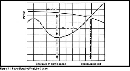
The best rate of climb speed is the airspeed that will afford the greatest gain in height in a given time. If it is important to reach a given altitude in the shortest possible time, this is the airspeed to use. The helicopter can be climbed at any airspeed within its operating limits, but the best rate of climb is obtained at the airspeed where power required for flight is at a minimum, and power available is near the maximum. Refer to the accompanying chart (Fig 5-1).
Prior to entering the climb, good airmanship dictates that you ensure that there is no traffic ahead and above. Remember that it may be difficult for an aircraft above to see you.
To enter a climb from cruise flight;
While in the climb monitor the engine temperatures and pressures, and maintain a constant lookout for other aircraft.
To level off from the climb:
Descents are commenced with a reduction in power.
Before commencing a descent it is important to conduct a good lookout to ensure that the area ahead and below is clear of other traffic as your forward visibility will be somewhat reduced in the descending attitude.
To proceed from cruise flight to a descent:
While in the descent, remember to scan your engine instruments to ensure that all temperatures and pressures are within limits, and keep a good lookout for other aircraft.
To level off from the descent to cruise flight:
It may also be necessary at times to enter a climb directly from a descent. In many light helicopters the airspeeds for both manoeuvres will be similar and therefore the attitude change, if any, will be small. Prior to proceeding from a descent to a climb, once again ensure that the area ahead and above is clear of other aircraft.
When your lookout has confirmed that the area is clear:
An easy guide to remember the climb and level from the climb is:
A. - Attitude - cyclic
P. - Power - collective
T. - Trim - adjust controls for balanced flight.
An easy guide to remember the descent and level from the descent is:
P. - Power – collective
A.- Attitude – cyclic
T.- Trim - adjust controls for balanced flight.
The turn is a basic manoeuvre used to change the heading of a helicopter. An accurate level turn may be described as a change of direction, maintaining a desired angle of bank, altitude and airspeed with no slip or skid. This is also the description of a co-ordinated turn.
To turn the helicopter, co-ordinate the cyclic, pedals and collective until a desired bank attitude is attained. The object of applying bank during a turn is to incline the lift so that, in addition to supporting the helicopter, it can provide the necessary centripetal force towards the centre of the turn to oppose centrifugal force, which is endeavouring to pull the helicopter away from the centre of the turn.
In a level turn, lift must be sufficient both to support the helicopter and to provide the inward force. Therefore, it must be greater than during straight and level flight. This additional lift can be acquired by increasing power or by sacrificing some airspeed to maintain your altitude.
For training purposes, turns are divided into three classes:
In addition to level turns there are:
Here are some basic facts you should understand:
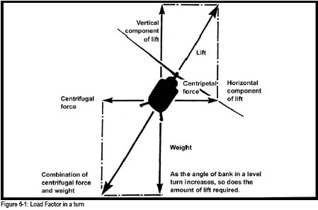
The resultant of weight and centrifugal force during turns produces an increased load factor on the helicopter. See Figure 6-1. Load factor may be described as the total load imposed on the helicopter, divided by the weight of the helicopter, and is expressed in G units. Load factor during a turn will vary with the angle of bank. Airspeed during the turn does not affect load factor, because for a given bank angle the rate of turn decreases with increased airspeed, resulting in no change of centrifugal force. Note that for a 60 degrees bank turn, the load factor for any helicopter is 2 G regardless of its airspeed (Figure 6-2 refers). This means that a 3000 lb helicopter in a 60 degrees bank turn will, in effect, exert 6000 lbs of force on the helicopter structure. Bank angles of up to 30 degrees will produce only moderate increases in load factor that are acceptable under most flight conditions that you will encounter. The load factor rises at an increasing rate at bank angles over 30 degrees, and may produce unacceptable disk load depending upon the helicopter gross weight and the prevailing flight conditions.
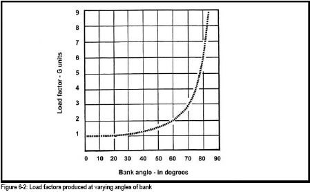
In turbulent air, severe vertical gusts can cause a sudden increase in angle of attack, resulting in increased rotor blade loads that are resisted by the inertia of the helicopter. All helicopters have a maximum permissible load limit that must not be exceeded. As a responsible pilot you should be aware of the limitations of your particular helicopter, and avoid situations that may cause the load factor to approach the maximum. Practically what this means is to avoid doing turns over 30 degrees when you are heavily loaded, especially in gusty or turbulent winds.
The importance of look out, searching the sky for other aircraft before and during a turn, cannot be over-emphasized. Before entering a turn, look around carefully in both directions, above and below. A casual glance is not good enough. During the turn continue to look out especially in the direction of the turn. When recovering from the turn, look around again, in both directions, above and below. To maintain a good lookout, and manage the helicopter at the same time requires the pilot’s constant attention.
Posture is important in all helicopter manoeuvres, and especially so in turns. Sit comfortably upright, do not lean away from the centre of the turn, nor should you make a conscious effort to keep your body stiffly vertical. Relax and ride with the turn. Stiffening up or continually changing sitting position affects visual references, and may cause handling of the controls to become tense and erratic.
An accurate level turn entry requires that the helicopter be flying straight and level as accurately as possible, prior to entering the turn. Any error made before entering the turn
is likely to be exaggerated as the turn develops. The same principle applies to turns while descending or climbing.
In making an accurate turn, the trained pilot co-ordinates the movement of all three controls so that the entry, the sustained turn, and recovery is made in one apparently simultaneous movement. Cyclic controls bank and pitch attitude, the collective controls altitude and the pedals prevent yaw.
To execute a turn from straight and level flight:
In a gentle turn, the position of the nose in relation to the horizon, which is the visual reference for pitch attitude, will remain relatively the same as in straight and level flight. However, as the angle of bank is increased, the attitude of the disc must be altered by backward pressure on the cyclic. This is to compensate for the added load factor imposed by centrifugal force as the turn steepens. The loss in airspeed, or the need for an increase in collective to maintain airspeed, becomes more apparent as the angle of bank increases.
As the helicopter settles into an accurate turn in co-ordinated flight:
One common fault when entering turns is excessive use of the pedals. This fault can be corrected quickly or completely prevented, if you remember right from the outset not to apply pedal unless it is necessary to control yaw. Normally you may need only a small pedal input into the turn.
To recover from a turn onto a pre-selected heading:
Climbing and descending turns are executed like level turns except that instead of maintaining a constant altitude, a constant climb or descent is maintained. The control inputs to enter, maintain, and recover from the turn are the basically the same as in level turns. Initially, climbing and descending turns will be entered from normal straight climbs and descents and the recovery made back to straight climbing or descending flight, to enable you to experience and readily observe the difference in pitch attitude necessary to maintain the desired airspeed. As you gain proficiency, these turns will be entered directly from straight and level flight, and recovery made directly back to straight and level flight.
The standard rate turn is a turn at the rate of 3 degrees per second. The rate at which a helicopter turns is determined by airspeed and angle of bank. At a given airspeed a specific angle of bank will provide a certain rate of turn. A simple way to estimate the angle of bank required for a standard rate turn at a given airspeed is to take 10% of the airspeed (mph) and add 5 to the quotient or add 7 to the quotient if the airspeed is in nautical miles (kt). For example, at 100 mph, (10 + 5) = 15 degrees of bank; at 80 kt, (8+7)= 15 degrees of bank.
During a turn, instrument indications are as follows:
TURN AND BANK INDICATOR. The needle will deflect in the direction of the turn and will indicate the rate at which the helicopter is turning. In a co-ordinated turn the ball will be centred in its curved glass tube. If the ball is off-centre to the inside of the turn, the helicopter is slipping into the centre of the turn. If the ball is off-centre to the outside of the turn, the helicopter is skidding out from the turn.
ATTITUDE INDICATOR. The horizon bar will remain parallel to the real horizon, and the miniature aircraft in relation to the horizon bar will bank in the same direction as the helicopter. This instrument indicates the angle of bank and the attitude of the helicopter in the pitching plane. The nose of the miniature aircraft in relation to its artificial horizon corresponds to the pitch attitude of the nose of the helicopter in relation to the real horizon.
HEADING INDICATOR. Immediately as a turn begins, this instrument begins rotating to indicate the successive new headings of the helicopter during the turn. When the turn stops, it stops. To decrease the numerical values on the face of the instrument turn left; to increase values turn right. A memory aid is “left for less”.
AIRSPEED INDICATOR. The instrument that does not perceptibly react until well into a co-ordinated turn is the airspeed indicator. Since the load factor increases as a result of the turn, additional lift must be obtained by tilting the rotor to the rear. In a gentle turn the decrease is barely noticeable, even in a well-executed medium turn the airspeed may be only slightly lower. If the nose is allowed to pitch up too high there will be a decrease in airspeed; conversely, if the nose is allowed to pitch down too low, the airspeed indicator will rapidly indicate an increase in speed.
ALTIMETER. In a co-ordinated level turn, the altimeter needle would remain stationary at the selected altitude. If the nose is held too high, there will be an increase in altitude. If the nose is allowed to drop too low, a decrease in altitude will be indicated.
An autorotation may be defined as the condition of flight where the rotor is driven by aerodynamic forces, with no power being delivered by the engine. Autorotational flight is a basic and essential emergency procedure at which every helicopter pilot must be proficient. Although modern helicopter engines and other major components are extremely reliable, pilots will ensure that they are capable of flying the helicopter under other than normal situations, including engine failure. During autorotation the helicopter is still flying despite the fact that the engine is not delivering motive power to the rotors. It remains fully manoeuvrable albeit in descending flight. Remember also that the airflow is now upward through the disc rather than downward as in powered flight. Prior to conducting this exercise, your instructor will review with you the manufacturer’s recommended airspeeds and rotor RPM for minimum rate of descent in autorotation. These speeds can be found in the aircraft flight manual.
This exercise will be your introduction to autorotations. In it you will be concentrating on the entry procedure, establishing a descent at the airspeed for the minimum rate of descent, and how to conduct an overshoot to the climb from the autorotational descent.
Good airmanship requires that, prior to carrying out autorotational descents, you must perform “pre-entry” checks, to include:
A memory aid for the checks is as follows:
H - Height - sufficient for exercise;
A - Area - good for landing if required;
S - Security - straps, no loose articles;
E - Engine - Temperatures and pressures; and
L - Lookout - Good look around especially below and check the wind velocity.
Once you have completed the pre-entry checks, you may now set up the helicopter for the entry to autorotation. Select an altitude that will provide sufficient height so that you will not be rushed, and that will give you plenty of time to experience the flying characteristics of the helicopter in autorotation. For the purpose of this exercise, establish the helicopter straight and level prior to the point where you will lower the collective; the airspeed should be at normal cruise. While it is not always possible to perform this manoeuvre into wind, during the early stages of autorotational training you should ensure that you are flying into the wind, and, of course, that the area below is clear.
NOTE: The policy of most schools is that they do NOT let students perform any autorotational exercise when solo.
To enter autorotational descent first lower the collective fully; to ensure that the rotor RPM does not exceed the manufacturers’ limits; smoothly roll off the throttle. It is important to make these movements smooth, so that you can anticipate the requirement for aft cyclic to prevent any nose down pitching moment, and at the same time, for a pedal adjustment to keep straight. The rotor RPM and engine RPM needles should be split at this point.
The helicopter will now begin to descend. Select an attitude with cyclic to decrease the airspeed from cruise to the manufacturer’s minimum rate of descent speed. You will see that just as in powered flight, the cyclic controls the heading and the airspeed. The collective controls rotor RPM in autorotation, raise it to reduce RRPM, lower it to increase RRPM. You must also maintain the helicopter in coordinated flight with the pedals. Flying with the ball out of centre
is aerodynamically inefficient and will adversely affect the airspeed and the glide distance.

Your instructor will have you carry out some turning manoeuvres. Particularly note that both the RRPM and the rate of descent increase, and that it may be necessary to raise the collective slightly to prevent a possible rotor overspeed. Later on you will learn how to use these two facts to vary your range in autorotations depending on the existing conditions. In any case you will want to roll off any bank, as soon as practical, to reduce the rate of descent and to prepare for the flare and landing. However, in this exercise you will be practising the overshoot while later lessons will deal with the autorotative flare and landing. During the descent you must check the temperatures and pressures are in the normal operating range and that the engine is still operating and will be available for you to commence your overshoot.
To make an overshoot from the autorotational descent, smoothly increase the throttle to rejoin the needles within the correct operating range. Be prepared to raise the collective as necessary to prevent any tendency for the rotor to overspeed. Once the needles are matched, raise the collective to set climb power and at the same time adjust the cyclic to achieve the best rate of climb. Anticipate the requirement for pedal to maintain the helicopter in co-ordinated flight throughout the transition from autorotational descent to powered flight. Once you have established a stabilized climb perform a post-takeoff check, ensuring all temperatures and pressures are in the normal operating range. This is important because you have been operating the engine at idle while conducting your autorotations.
Your instructor will demonstrate straight-ahead and turning autorotations. You will have the opportunity to practise entries, descents, and overshoots for these types of autorotations. While it is important to react quickly in the event of an engine failure, or other emergency requiring an autorotation, at this stage of your training the emphasis should be on smoothness and accuracy.
While carrying out previous exercises, you have undoubtedly observed your instructor perform various hovering manoeuvres. Prior to starting this exercise your instructor will review the following ground school points:
You may remember from ground school that the helicopter requires considerable power to hover. Therefore, it is important that you ensure that there is sufficient power available and that you monitor engine temperatures and pressure throughout all hovering manoeuvres.
The importance of lookout has been stressed in previous exercises. Lookout is extremely important when hovering. You will be flying near the ground so you must keep a sharp lookout to avoid accidentally flying into any obstacles.
A large, flat, open field, free of obstacles, should be selected for all hovering practice. Ensure that the surface is firm, and there is no loose material such as sand, snow, cut grass, or leaves, which the rotor wash may blow up and which might be ingested by the engine.
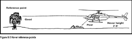
Light single-engine helicopters generally hover with the skids 3 to 5 feet above ground. This height will ensure that the skids are well clear of the ground and any low obstacles, and will also allow you to land safely should you ever have an engine failure. Take note that a normal hover at 3 to 5 feet will require less power than a hover at 10 feet.
Hovering is defined as maintaining a constant height and heading over a given position on the ground. In a previous lesson you learned the effects of controls in cruise flight. These effects are very similar in the hover.
In a hover, the cyclic is used to maintain a fixed position over a spot on the ground. As a recall, the cyclic controls disc attitude. A change of disc attitude will be followed by a change in fuselage attitude and, in hovering flight; this will cause the helicopter to move horizontally across the ground. For example, moving the cyclic forward or aft will cause the nose to drop or rise and the helicopter will move forward or backward. Similarly, moving the control to the left or right will cause the helicopter to move over the ground to the left or right.
In most types of helicopters there is a slight time lag between cyclic movement and aircraft response.
To cease horizontal motion and to regain a steady hover requires two cyclic movements; one to stop the movement, and a second to stabilize the helicopter in the hovering attitude. For example, if you note the helicopter is moving rearward the following cyclic movements will be required; the cyclic would be moved very slightly forward to stop the rearward movement, and then centralized in a position that maintains the helicopter in a steady hover.
The cyclic in the hover is more sensitive than in forward flight. A very small cyclic control movement will result in a very large helicopter movement. Your instructor will demonstrate this sensitivity of the cyclic in hovering flight.
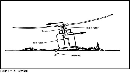
North American helicopters usually hover with a left skid low attitude. This is caused by Tail Rotor Roll, which will be reviewed by your instructor (Fig 8-2).
In the hover the collective is used in the same manner as in forward flight. The collective controls the height of the hovering helicopter above the ground. Raising the collective will result in an increase in helicopter hover height and a decrease in hover height will result if the collective is lowered.
Secondary effects of controls will also be noticed in the hover. Raising the collective will result in an increase in torque and this will cause the helicopter to yaw to the right. A yaw in the opposite direction will occur if the collective is lowered. In addition, if you are flying some piston engine helicopters, the throttle may have to be adjusted to maintain RPM as the collective is raised or lowered.
During hovering flight the anti-torque pedals are used to maintain or change the helicopter heading. In the hover, the effect of torque is more noticeable than in forward flight. Therefore, the nose of the helicopter will tend to yaw more in the hover, and this has to be countered with opposite pedal pressure. To turn left in the hover, left pedal is applied, and the reverse is true for a right turn.
NOTE: In a piston engine helicopter, the throttle may have to be increased slightly as left pedal is applied, and decreased as right pedal is applied.
In a hover any change in attitude, if not corrected, will cause the helicopter to move. You must recognize any changes in attitude and make the necessary control corrections before the helicopter moves. Initially, it may be difficult to recognize these changes. As in upper air flying, it may be easier to first use the horizon as a reference, and then as you become more proficient focus your eyes on a reference closer to the helicopter (approximately 50 feet).
The cyclic is used to control the disc attitude, and therefore the helicopter position over the ground. Height is controlled with collective, and the pedals are used to maintain directional control. In a piston-engine helicopter, the throttle may have to be adjusted as pedals or collective are moved.
NOTE: The secret to mastering the skill of hovering a helicopter is to use very small, smooth control movements and lots of practice.
In this exercise you will learn how to take off to and land from the hover. It is important for reasons of safety of flight that you should be able to perform this manoeuvre accurately, as any lateral drift could cause a rolling moment if ground contact is made, possibly leading to dynamic rollover. Similarly rearward movement is undesirable, as you cannot see behind you and the tail rotor could be severely damaged should contact be made with an obstacle.
Before takeoff, the pre-take-off check should be completed, and you must look out to check the surroundings.
After every takeoff, a hover check must be completed.
Prior to landing, the area must be checked to ensure it is free of obstacles and the landing surface is suitable.
If possible make your takeoffs and landings into wind.
The effects of controls for takeoff and landing are the same as for hovering. They are used as follows:
It is important that your eyes be focussed outside on normal hover references. Glance quickly in at the console to monitor engine instruments.
Immediately after the aircraft is in the low hover (approximately 6 inches) a “hover check” is completed, then proceed to normal hover height. The check may vary with helicopter type, but must include the following items:
A normal landing is initiated from a 3 to 5 foot hover with the helicopter facing into the wind if possible.
The controls are used as follows:
It is important that you start the landing from a stable hover. From the hover, start a slow rate of descent with collective. As the helicopter approaches the ground, you will have to lower the collective slightly more to compensate for increased ground effect. Throughout the descent, heading and hover position are maintained with pedals and cyclic. For safety reasons, it is important that the helicopter does not touch down with sideward or rearward drift to avoid dynamic rollover. As the helicopter skids touch the ground, continue to slowly lower the collective to flat pitch, and then centralize the cyclic and pedals. Remember that the left skid will touch the ground first for North American produced helicopters and vice versa for French helicopters.
If you have problems maintaining control during the landing, smoothly climb back to a normal hover, then stabilize the hover prior to initiating another landing.
In this exercise you will learn how to perform the following manoeuvres:
Manoeuvring close to the ground is very much part of the helicopter environment and you will find that these manoeuvres are carried out as a matter of course.
During the exercise, bear in mind the following airmanship points to include that you:
Begin your pedal turns from a stable hover, preferably with the helicopter facing into wind. Look out to ensure the surrounding area through which the tail rotor will pass is clear of obstacles that could present a hazard. Start the turn by applying pedal to rotate the helicopter in the desired direction: to turn left apply left pedal, to turn right apply right pedal. Control the rate of the turn with pedal; that is: less left pedal to reduce the rate of a left turn, and vice versa. The amount of pedal required will vary with the strength of the wind. To stop the turn, apply opposite pedal, and then stabilize using pedals as required maintaining the heading. In strong winds weathercocking will cause the rate of turn to increase as the nose passes 180 degrees to the wind. Throughout the turn the cyclic is used to maintain position over the ground as you learned in previous hovering exercises. If there is a wind, the helicopter will tend to drift downwind; therefore you will have to displace the cyclic into the wind to counter this tendency during the turn. The stronger the wind the more cyclic is required.
Collective is used to maintain height in the turn. In strong winds, more frequent power’s changes will be required to maintain height.
In some piston engine helicopters the throttle may have to be adjusted to maintain the correct operating RPM as you manipulate the pedals and collective during the turn.
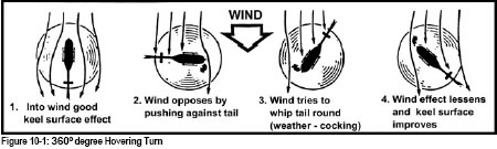
It is important that you anticipate the effect of the wind, as the helicopter will tend to align itself with the wind direction. This “weather-cocking” effect is caused by the wind pushing against the vertical fin and body in the same fashion as a weather vane. This will cause a variation in the amount of pedal required as the turn progresses through a full circle, and is most noticeable when the helicopter is at 90 degrees to the wind direction (Fig 10-1).
The continuous use of high power in this exercise means that a careful watch should be kept on the engine temperatures and pressures. Prolonged hovering out of wind, specifically downwind should be avoided because of carbon monoxide poisoning. Check the helicopter flight manual for any such limitations.
In strong gusty wind conditions a turn away from the into-wind position should be opposite to torque reaction, i.e.: to the left in a North American helicopter. In this way you will ensure that there is sufficient tail rotor control available. Should control limits be reached at this stage, a safe turn back into wind can be accomplished.
Light single engine helicopters are hover-taxied at the normal hover height of 3 to 5 feet skid height. For safety considerations it is desirable to hover-taxi at a slow speed; approximately a normal walking pace. This is important as:
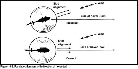
To begin taxiing ease the cyclic slightly forward, and as the helicopter begins to move, adjust the cyclic to maintain a walking pace. The pedals are used to maintain an accurate heading. In crosswind conditions, a combination of pedals and cyclic will be required to keep the helicopter moving in a straight line across the ground (Fig 10-2). The skids should be tracking parallel to the direction of movement. Collective is used to maintain a constant height throughout the manoeuvre. When taxiing downwind, it is important that you control the ground speed to maintain the walking pace.
To stop forward movement, ease the cyclic slightly aft. It will be necessary to anticipate where you wish to stop because of the lag between cyclic input and helicopter response. This is due to the inertia of the helicopter itself. Make the required cyclic movement small; there is no need to flare the helicopter.
All cyclic movements should be small and smooth; avoid rapid and excessive aft applications of cyclic to ensure that you do not put the tail rotor in jeopardy.
If you are flying a piston engine helicopter, the throttle may have to be adjusted to maintain the correct RPM as the collective and pedals are manipulated.
Although modern helicopter engines are extremely reliable, there is always the possibility of a failure, however remote. As a helicopter pilot, you must train for this possibility, and in this exercise will learn how to deal with an engine failure while operating your helicopter in the hover or the hover-taxi. The operational helicopter pilot spends a considerable amount of his working flying time in the hover environment, performing a variety of tasks, and he must therefore be competent to handle this type of emergency safely and efficiently.
You should not refer to this manoeuvre as an autorotation. When the engine fails at the hover there is insufficient height to successfully enter autorotative flight. Were you to lower the collective lever, the helicopter would sink rapidly to the ground and would likely suffer damage. If the engine should fail in the hover, the rotor does not immediately cease to rotate, but will gradually slow down due to drag. However, it still possesses a considerable amount of energy and inertia at the moment of engine failure that can be used to cushion the helicopter onto the ground.
In the hover, when an engine failure occurs, the helicopter will instantly yaw to the left as engine torque is removed (counter-clockwise rotating rotor). Apply right pedal immediately to correct yaw. It will also drift to the left as the tail rotor thrust is diminished. You will remember that you compensate for tail rotor thrust in the hover, by holding a small amount of left cyclic, to prevent the helicopter drifting to the right. When the tail rotor thrust is removed then the left cyclic will cause a drift to the left. Should you be hovering into a wind, the helicopter will also tend to drift to the rear as the main rotor thrust is reduced. Lastly, the helicopter begins to sink due to the reduction in lift produced by the main rotor.
The pilot must compensate for the above reactions prior to touchdown, as it is possible for a rollover to occur if drift, or yaw, is present during the landing. Collective should be increased as required to cushion the touchdown.
Should an engine failure occur while you are in the hover-taxi, the helicopter reactions will be the same except, of course, for the existing forward speed. It is most important that aft cyclic is not applied in an effort to arrest forward movement, as there is a real danger of striking the tail rotor as the helicopter settles to the ground. Touchdown with some forward speed is quite acceptable, and in most cases the helicopter is run forwards onto the ground.
Your instructor will demonstrate the sequence of events to you and the desired pilot reaction:
This exercise is the basis of many others and the skill learned will be used in almost every flight you make from now on in your career. Your instructor will review:
The manoeuvres that are employed to accelerate the helicopter from the hover to forward flight, and decelerate it from forward flight to the hover, are known as transitions. In fact all accelerations or decelerations of the helicopter in any direction as a result of cyclic change are transitions.
During this exercise, you concentrate on performing smooth and accurate transitions. The ability to perform accurate transitions is important in the working environment of the helicopter pilot.
Remember to carry out a careful lookout during this exercise and to perform a clearing turn prior to each takeoff. Do this by turning 90 degrees right or left and observing that the approach area is clear of other aircraft.
Begin the transition to the climb from a steady into-wind hover at normal hover height (Fig 12-1):
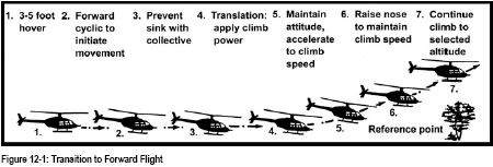
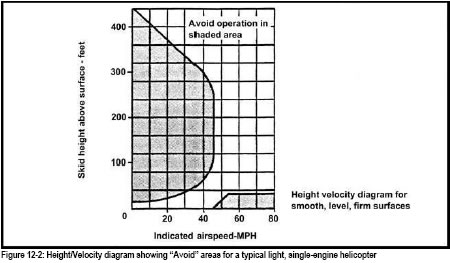
As effective translational lift is achieved the nose will tend to rise and the helicopter will want to climb. Remember to stay within the take-off corridor of the Height/Velocity diagram. Forward cyclic may be required to prevent the helicopter from climbing into the “Avoid” curve. In winds of approximately 15 mph or more, flapback will not be encountered as the helicopter is already experiencing translational lift (Fig 12-2).
During this exercise, your instructor will demonstrate the effects of flapback if it is not compensated for with additional forward cyclic during the transition.
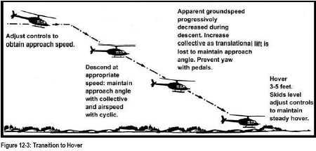
This transition is the standard type of approach to a hover or to a landing that will be utilised throughout your training and your career. (Fig 12-3)
The manoeuvre requires that you combine two separate actions in a co-ordinated procedure to achieve:
The height of the helicopter has to be reduced from the approach altitude, (this may be circuit height, cruise altitude or whatever altitude you are flying at), to hover height above ground. Ideally this is a constant angle, straight-line type of approach, which can be made with little change of attitude and gradual changes in power.
The approach speed must be progressively reduced to zero groundspeed as you arrive at the hover. Since different approach angles or wind conditions will cause the airspeed to vary, refer to groundspeed, and not airspeed as indicated on your instruments. A good guide for approaching the touchdown point is to fly so that the helicopter appears to be moving across the ground at a walking pace. If you are able to maintain this visual perspective, your groundspeed will be constantly reducing throughout the transition to the hover.
To begin the transition to the hover, after ensuring the approach path and the landing zone are clear of other traffic, set the helicopter up straight and level, into wind, at a specific height and airspeed. For training purposes a minimum of 300 feet is desirable, with speed appropriate to type:
On occasion, it may be necessary to carry out an overshoot from the transition to the hover; this is also a valuable co-ordination exercise. To perform this manoeuvre:
In Exercise 7, you learned how to enter autorotative flight and establish the descent at the minimum rate of descent speed for your helicopter type. You also learned that the helicopter is fully manoeuvrable in autorotation and that turns can be made just as in powered flight. In this exercise, you will learn how to carry out the landing from an autorotational descent in a safe and effective manner.
In addition, you will learn how to perform a “power recovery” in the event that the “full-on” landing may be unsafe due to aircraft performance, inappropriate landing area, a lack of suitable wind or a high-density altitude. The power recovery may be performed to either the hover, or the hover-taxi and is a good coordination exercise and should be practised when it is not possible to perform full-on autorotations. “Power recovery” autorotation is not a substitute for the full-on autorotation. It is essential to practise full-on autorotations to become safe and competent.
In preparation for this exercise, perform the pre-entry H.A.S.E.L. checks that were learned in Exercise 7.
After completing the pre-entry checks, manoeuvre the helicopter to a position, which will allow the safe completion of the full-on autorotation. When in position, smoothly lower the collective and roll the throttle to idle. Adjust the cyclic to acquire the minimum rate of descent speed and remember to compensate both for the yawing and the nose-down pitching moments that occur when the collective and throttle are reduced. During the descent, further adjustment to the cyclic and the collective may be necessary to maintain both the desired speed and the Rotor RPM within limits.
At approximately 50 to 100 feet, depending on the type, a flare is initiated. The purpose of this manoeuvre is threefold: to reduce forward speed, rate of descent, and increase Rotor RPM. Commence the flare by applying aft cyclic, keeping straight with pedals. Your instructor will demonstrate to you the effects of applying too much aft cyclic; this will usually result in a climb. Conversely, little flare will not reduce efficiently the forward speed and the rate of descent. In this case, the landing speed will be much greater than desirable, giving the possibility of damaging the helicopter during a fast ground run or the possibility of the helicopter striking its tail.
The flare should be maintained until the forward speed is reduced to that desired for the landing, and the helicopter’s height has decreased to between 10 and 25 feet, depending on the type. At this point the helicopter is levelled in preparation for the touchdown. Note that it is a level attitude we must achieve, as landing with a nose, or tail-low attitude would cause damage to the helicopter, as a rocking motion will be set up upon touchdown. A nose-low attitude caused by too much forward cyclic will cause the helicopter to accelerate again, resulting in a faster touchdown speed and a longer ground run. Ensure that the skids are aligned with the direction of travel so that you do not land with any lateral motion. In other words, keep it straight with pedal.
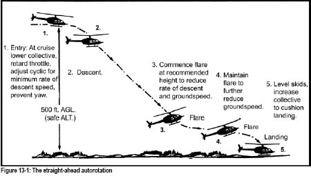
The helicopter will now begin to descend vertically. Apply collective pitch as necessary to arrest the descent, and to cushion the helicopter on to the ground. Maintain the heading with pedals, and do not lower the collective until after all forward motion has ceased. You must also maintain the cyclic in a neutral, or slightly forward, position to preclude the development of a rocking motion if running on. Once you have come to a stop, lower collective fully, neutralize the pedals, and carry out a check of the instruments prior to increasing throttle in preparation for the takeoff.
As previously discussed, there may be occasions when it will not be prudent to conduct full-on autorotations, but you may wish to practice the techniques by performing an autorotational descent to a power recovery.
Enter autorotation as for a full-on, then, at a safe height, increase the throttle to rejoin the needles and bring the RPM into the correct operating range. This increase in power will cause the helicopter to yaw, anticipate this and apply pedal to prevent it. Initiate the flare at the appropriate height just as you did for the full-on autorotation. Maintain the heading with pedals and the flared attitude with cyclic; at the appropriate height, level the helicopter. Collective pitch must now be increased to check any tendency to sink and to achieve a steady hover, or hover- taxi, as the case may be. Throughout the manoeuvre prevent yaw with pedals. You may now carry out a normal transition to a climb. It is important that your throttle and collective movements be smooth and coordinated as it is possible to exceed Engine and/or Rotor limitations during this manoeuvre. Prior to moving on to the next exercise, or manoeuvre, ensure that you complete a check of the engine instruments.
While modern helicopters are extremely reliable, emergencies requiring prompt pilot action occasionally do occur. Therefore, pilots must have a thorough understanding of the helicopter systems, and must repeatedly practice the handling of in-flight emergencies under simulated conditions, so that they are prepared to successfully handle a real emergency should one occur.
In this air exercise your instructor will acquaint you with the particular emergency procedures as they apply to your type of helicopter. These may include:
There are also a number of caution advisory lights in most modern helicopters which, when illuminated, give the pilot warning of a malfunction. The pilot’s reaction will vary according to the type of helicopter and the particular malfunction, but should generally include a precautionary landing. Indeed it is prudent and shows good airmanship to make a precautionary landing whenever unusual instrument indications are noticed, or when vibrations, noises or control forces that are out of the ordinary occur. Even if the helicopter appears to be operating normally in all other respects, it makes good sense to land and investigate.
Once having made the decision to carry out an emergency or a precautionary landing, these actions should be followed:
Throughout your training, you will continue to practise simulated emergencies and malfunctions until your reactions to them become instinctive.
This exercise is to learn how to fly an accurate circuit practising all the manoeuvres that you have previously been taught. Your instructor will emphasize the need for precise airspeeds, altitudes, and headings when flying this exercise.
The circuit is of less importance in helicopter operations than in fixed wing flying. Nevertheless, it is valuable training exercise that consolidates all previous air exercises into one convenient package. Through practise of the circuit you will develop accuracy in all aspects of your flying.
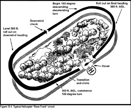
Circuit patterns may vary in shape depending on local conditions and training requirements; your instructor will describe, and demonstrate, the one most appropriate to the helicopter type and the school location. The examples described here are referred to as a “racetrack” and a “square” probably the most commonly used helicopter training circuits (Fig 15-1 and 15-2).
Unless noted, Canadian Aviation Regulations require all circuits to be left hand, but often ATC will request a right hand circuit for separation from fixed wing circuits. Since it is likely that you will be flying your circuits in proximity to other aircraft, lookout is very important. Ensure that you perform a clearing turn prior to each transition to forward flight, and that you maintain a good lookout while flying the circuit itself. Although your instructor will emphasize accuracy, do not sacrifice a good lookout because you are concentrating on the instruments in an effort to achieve that accuracy.
Radio communications in the circuit will be performed as per tower instructions or per uncontrolled aerodrome procedures.
Choose an area for circuits that allows an into-wind takeoff and an approach path that is clear of obstacles. Before taking off, take note of the following:
Lift the helicopter into the hover and perform a clearing turn, commence a standard transition, and:
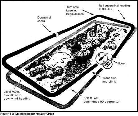
The square circuit varies slightly from school to school as far as heights to fly but the basic pattern is the same. The example below is just one variation.
Lift the helicopter into the hover and perform a clearing turn, commence a standard transition, and:
It is extremely important that you be constantly aware of the position of other aircrafts that may be operating at the same location. This is of even greater significance if there are fixed and rotary wing aircraft operating at the same airfield. You must fly your circuit taking into account other helicopters that may also be conducting circuit practice, and maintain a suitable distance from them. You may have to change your touchdown spot so that you do not interfere with their operations. Remember that displaying courtesy is also good airmanship. If you are operating at an airfield where there is a mix of both fixed and rotary wing, the exercise of good judgement and consideration for other pilots becomes most important. It will likely be necessary for you to arrange your circuit to remain clear of the fixed wing circuit, but seek approval from the ATS to fly a circuit opposite to that being flown by the aeroplanes. This may also mean that you may not be able to arrange the circuit so that you are directly into wind for the takeoff and approach. You may not encounter this difficulty at an uncontrolled airfield, but in any event, you will find that the ability to arrange your circuit so that it causes no disruption to other traffic, will not only be appreciated by other pilots, but will result in safe flight operations.
Numerous aircraft incidents and accidents occur at the busier airports as a result of wake turbulence, despite the many studies on the subject and the increased publicity among the pilot community. While these occurrences primarily involve light aeroplanes, the helicopter is also vulnerable if the pilot selects a flight path that intrudes upon the turbulence generated by airflow from the trailing edge of an aerofoil.
The vortex generated by an airfoil is proportional to the lift generated by the airfoil, its size, and angle of attack. The ratio of aircraft weight to aerofoil size also has a bearing on the vortex produced. A heavy aircraft with a small wing (and therefore a high wing loading) will produce intense vortices, while the longer and broader the aerofoil, the greater the area affected by the vortices.
This same principle applies to helicopters. Helicopter rotors trail the same twin vortices as a fixed wing aircraft, and the greater the helicopter’s weight, the more intense will be its wake turbulence.
Speed affects the vortices inversely; that is: an aircraft flying at a slow speed will produce more intense vortices than when it is at cruise. We would therefore expect to encounter the most intense wake turbulence when aircraft are landing or taking off, although an S61 flying at 20 kts will also produce intense vortices while not necessarily landing or taking off.
These vortices tend to descend below the path of the aircraft producing them and spread apart. A wind, of course, will affect the vortices causing them to drift downwind, dissipating slowly in calm winds, and dissipating more rapidly in strong winds. It should be noted, however, that the movements of the vortices are not predictable with any degree of certainty.
To avoid encountering wake turbulence, the helicopter pilot should select approach or departure paths that are above the departure path of other, larger aircraft. Also, he should avoid selecting any flight path that would cause him to intersect the arrival or departure path of any aircraft capable of creating strong vortices, and particularly avoid below the flight path of other aircraft.
Control zones have been designated around certain aerodromes to keep IFR aircraft within controlled airspace during approaches and to facilitate the control of VFR and IFR traffic. Control zones within which a radar control service is provided normally have a 7-mile radius. Others have a 5-mile radius, with the exception of a few which have a 3-mile radius. Control zones are capped at 3000 feet above airport elevation unless otherwise specified.
VFR aircraft require a clearance from an air traffic control unit or to establish contact with an ATS to enter a control zone. This clearance or instruction, however, does not relieve the pilot of responsibility for avoiding other aircraft, maintaining appropriate terrain and obstruction clearance, and remaining in VFR weather conditions. It is also a requirement that the aircraft be equipped with radio communication equipment capable of two-way communication with the appropriate air traffic control unit. In certain instances, NORDO operations may be authorized. You should consult your A.I.M Canada for details.
When you intend to conduct flight training exercises within a control zone, the ATS will likely ask that you:
If you intend to depart the control zone, you should advise the ATS of your intentions, and they in turn will advise you when to leave the frequency.
Many control zones have established reporting points that VFR traffic may use to identify their position when transmitting to the ATS.
Your instructor will explain the procedure for using Mandatory Frequencies (MF) and Aerodrome Traffic Frequencies (ATF). At uncontrolled aerodromes, although there will not be an operating control tower, a Flight Service Station may be in place. The FSS does not exercise control over air traffic but only acts in an advisory capacity, providing information on winds, runway in use, known traffic, weather, etc. Some airfields will not be equipped with either a tower or a FSS, but will only have a “Unicom” frequency that may or may not be monitored. At uncontrolled aerodromes, pilots must use the appropriated frequency to transmit position reports and broadcast their intentions while operating in the zone.
The first solo is a landmark in your flying career. You will never forget it and it is quite normal to look forward to it, but do not exaggerate its importance. It is not so much when you solo, but rather what you know and what you can do correctly at this stage of training that is important. Soloing is merely another step in the orderly process of training, bringing you to the stage where learning really begins.
Before being permitted to take your first solo flight, you will have to demonstrate to your instructor that you are able to:
As pilot-in-command you are responsible for the operation and safety of the helicopter during its flight time on solo flight. However, for this first solo your instructor will ensure that suitable conditions exist and precautions are taken. For example:
Ensure that you securely fasten the seat belt and shoulder harness, if fitted, of the empty seat, so that there is no chance of the belts interfering with the collective or cyclic.
On a solo flight, you will notice that the lateral CG shifts somewhat and that the takeoff and transition will appear to be more rapid as the helicopter will be significantly lighter. This was the most noticeable feature of the first solo flight.
For a given power setting, you will find that the helicopter will climb much more rapidly and that a somewhat greater collective reduction is necessary to initiate a descent.
New manoeuvres and procedures will be added as progress permits, and further solo flights planned at intervals throughout your training. Specific practice on previously learned procedures, as well as new, will be included in these solo flights. When authorized and briefed to do specific manoeuvres, it is important that you practise this specific work diligently in order to develop safe flying skills. The objective of any solo flight must be to attain greater precision, co-ordination and judgement.
One of the unique abilities of the helicopter is that of being capable of moving over the ground in a sideways or backwards fashion. For the pilot, the ability to fly the helicopter in this manner is fundamental to exploiting its manoeuvrability to the maximum.
If conditions allow, it is always preferable to hover-taxi forward rather than sideways or to the rear. It is obvious that your visibility is much better when facing forward than if you were moving in another direction and you will therefore be better able to identify and avoid obstacles that may intrude into the flight path. You will also be better able to handle an engine failure when the helicopter is moving forward with the skids tracking across the ground parallel to the direction of movement. It is important, during any hovering manoeuvres, to maintain a proper hover height. A number of manufacturers recommend 3 to 5 feet skid height. Helicopters with low inertia blades should generally be hovered at a lower skid height. In any case, the height should not be so low that the skids are in danger of contacting the ground or small obstacles, since a rollover may result if the helicopter is in motion.
When hover-taxiing your helicopter, maintain a speed that is about the same as a normal walking pace. Any faster and you may begin to encounter effective translational lift; control of the height will then be somewhat difficult as the helicopter will want to climb. Should this occur when taxiing sideways or to the rear, it is possible to exceed the manufacturers airspeed limitations for those directions. Fast taxiing to the side or rear will require judicious use of pedals to counter any weathercocking tendency. Remember that flapback can occur in any direction, not just in forward flight, and the pilot will have to overcome it in the usual manner when hovering to the rear or to the side.
To commence sideways flight from the hover, proceed as follows (Fig 16-1):
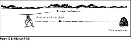
4. apply pedals as necessary to maintain heading and prevent yaw or weathercocking;
5. adjust the cyclic as required to overcome flapback and to keep the helicopter moving at a smooth, constant rate; and
6. alternate between looking forward to ensure the helicopter remains on the original heading and in the direction of movement for any obstructions.
To bring the helicopter back to a hover:
Before commencing rearward flight, do a clearing turn of 90° or 180° to ensure that there are no obstacles in the proposed flight path, and to identify the point at which you will cease your rearward flight. Once you are satisfied that the area is clear, return to your original heading and after picking you reference points:
To return the helicopter to the hover:
In the operational environment, there is seldom the need for lengthy rearwards hovering-taxi and if for some reason you must do so, it is good airmanship to periodically stop and do another clearing turn to check that the area is clear of obstructions. Be aware that in both turbine and reciprocating engine helicopters, exhaust fumes can enter the cockpit under certain wind conditions while hovering to the rear.
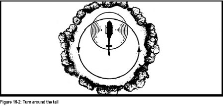
This is a useful manoeuvre from an operational standpoint (Fig 16-2) and you will find that it is often used when required to re-position the helicopter within a confined area. The techniques are similar to those, which you employed in sideways hovering (See figure 16-1).
To commence this manoeuvre, look first in the direction that you intend to turn, ensuring that the area is clear of obstacles that could pose a hazard to the helicopter. While doing this, try to imagine that the cockpit of your helicopter is sitting astride the circumference of a circle with the tail of the helicopter at the centre of that circle. Unlike a turn around the mast, where in still wind the turn can be completed with pedal alone, you must now co-ordinate both the pedals and the cyclic to move the helicopter around the imaginary circle. Use the pedals to keep the tail over the centre while maintaining a slow walking pace laterally with the cyclic. Collective is used to maintain the normal hover height. Be aware that in any wind conditions the cyclic must be displaced into the wind.
(Fig 16-3) This variation on the hovering-turn, you will also find extremely useful in the operational sense. To practice the manoeuvre, identify a spot on the ground close to nose of the helicopter; 10 to 15 feet will suffice. Avoid selecting a spot close in, as you will find, as in basic hovering, that it will be difficult to accurately control your height. Look in the direction you intend to move the helicopter to ensure the entire area is free of obstacles. The manoeuvre itself is similar to the turn around the tail, except the tail now sits astride the circumference of the imaginary circle.
Use the pedals to keep the nose pointed at the selected spot while effecting lateral movement with the cyclic. Maintain the correct hover height with the collective. Keep the movement slow and smooth as rushing turning manoeuvres will result in overcontrolling and you may exceed manufacturer’s limitations.
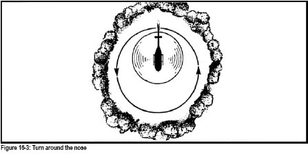
Steep turns are a means of turning the helicopter in a relatively small area. The practice of these manoeuvres is excellent in developing the coordination of all three flight controls and the power control. It is important that you acquire the ability to execute them accurately and smoothly. Your instructor will demonstrate them in different operational flying situations.
Up to a limited angle of bank a steep turn may be executed without increasing power. However, in order to maintain a constant altitude, the airspeed must be sacrificed as a result of the increased aft cyclic pressure required to maintain that altitude. Remember that the greater is the angle of bank, the greater the amount of lift is required to maintain a constant altitude, therefore, additional lift is provided by an increase of power.
A steep turn is entered like any other turn but, as the angle of bank is increased beyond approximately 30°, you must increase collective in order to maintain height and airspeed.
It requires simultaneous co-ordination of all three controls. Because of the rapid change of direction, the lookout for other aircraft before doing a steep turn is even more important than for other turns.
To enter a steep turn, first look out, then apply lateral cyclic in the direction of the desired turn and:
To recover from a steep turn, proceed exactly as you would for any other turn, except that, as you roll off the bank, the collective should be reduced simultaneously with the return to straight and level flight. You must also relax cyclic backpressure to ensure that the helicopter does not climb as you roll out of the turn. Remember that these movements should be coordinated and smooth.
Should you find that the nose of the helicopter is tending to pitch down while in the steep turn, do not attempt to correct by applying cyclic backpressure alone since this will only serve to tighten the turn. Use lateral cyclic to reduce the angle of bank slightly, then correct the attitude with coordinated aft cyclic. Another frequent error is the application of too much aft cyclic before it is required when rolling into the steep turn, causing altitude control to be erratic.
In preparation for this exercise, you should review the two previous air exercises on autorotations, Exercises 7 and 13.
In the preceding autorotational exercises, you found that to achieve the minimum rate of descent in most helicopters, you fly the autorotations at the manufacturer’s recommended airspeed. However, under emergency conditions, this airspeed will not necessarily result in your reaching your chosen landing spot. In fact, under actual emergency conditions, it will often be necessary to vary the airspeed, change the direction of flight, or employ some other combination of airspeed and turns in order to reach the spot. For example, should the landing spot be a small clearing in a wooded area, considerable manoeuvring may be necessary if you are to effect a safe landing. For this reason, you should take advantage of the helicopter’s capabilities in autorotative flight.
Prior to conducting an exercise of autorotations, it is recommended to roll off the throttle once while the helicopter is on the ground. This will confirm that the clutch or freewheeling unit is operating correctly, and that the engine is not going to quit. Always choose a large, level area for the full on with plenty of safety margin.
In the air, a confirmation of the selected area should be followed by the HASEL check.
Prior to conducting this exercise, your instructor will review with you the speeds, rotor RPM, and VNE according to your helicopter type. The maximum range speed will also vary depending on the helicopter types. (Refer to Figure 18-1).
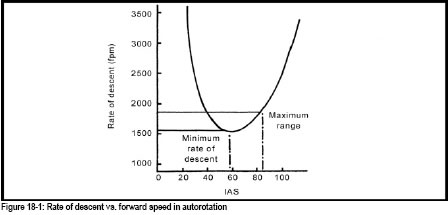
Many helicopter manufacturers specify a maximum autorotation range speed in their flight manuals (Fig 18-2). It is this speed that you should reference when performing this exercise. There is certainly no purpose in exceeding that speed, as after that point, no increased range will result. Indeed rate of descent will increase range will decrease.
You will also note that, although the rate of descent is higher, the distance covered over the ground is appreciably greater.To enter and practise a range autorotation, after completing the checks, proceed as follows:
Try to return to the minimum rate of descent speed as early as possible (by 200 feet AGL). Should you hold the maximum range speed down to flare height, you would find that the flare would have to be maintained longer in order to reduce the ground speed to acceptable level for the touchdown.
By reducing RRPM using collective the range can be further extended, but the rotor tachometer has to be closely monitored (Fig 18-2). In this instance, it is even more important to return to normal autorotation limits as soon as the landing spot is assured.
You will learn two methods of reducing the range in autorotation during this exercise:
The procedures are the same as other autorotations until after the entry, then as the helicopter enters autorotation, apply aft cyclic to reduce airspeed. It is possible to perform an autorotation at zero airspeed, but the rate of descent increases rapidly, and yawing may develop that is difficult to control because of loss of `keel surface effect’. During low speed autorotations it is permissible to have a negative groundspeed but NEVER a negative airspeed, so be sure to maintain some indicated airspeed. Select a reduced airspeed that will enable you to make your selected landing spot. You will practise this manoeuvre with speeds down to 10-15 mph with your instructor.
Notice that the rate of descent, in this type of autorotation, is significantly higher than with one flown at the minimum rate of descent speed. For that reason, it is important to increase the airspeed, to that for minimum rate of descent, as soon as you are assured of reaching the selected touchdown spot. This will have the effect of reducing the rate of descent to that which will allow you to safely flare the helicopter and land. Remember to abide by the height/velocity diagram when performing autorotations. Therefore, ensure that the airspeed is increased to the minimum rate of descent speed in order to remain outside the “Avoid” areas. As a rule of thumb to increase airspeed by 10 mph requires 100 feet of altitude.
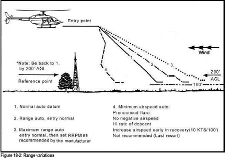
2. Turning (Fig 18-3):
It is also possible to shorten the range of an autorotation by turning the helicopter. When using turns to reduce the range, bear in mind that the increased disc loading can cause a rapid increase in the RRPM. Monitor the RRPM to ensure that the limits are not exceeded; it may also be necessary to raise the collective slightly to prevent overspeeding the rotor, but reduce it again as soon as possible to conserve RRPM for the landing.
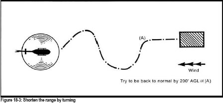
In addition to shortening the range of an autorotation, turning will greatly increase the rate of descent. Consider this fact when judging the distance to the desired touchdown spot, as this will determine what type of manoeuvre will allow safely reaching that spot. Figures 18-4, 18-5 and 18-6 represent different examples of turning autorotations.
Rates of descent in tight-turning autorotations can build up to more than 2500 feet per minute in some types of helicopters.
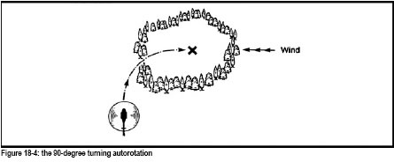
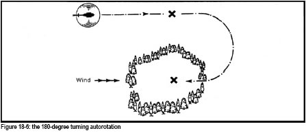
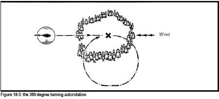
Practice forced approaches, as the name suggests, are the practical application of the autorotation and emergency exercises which your instructor has previously taught you.
During this exercise, you will be shown how to apply these skills to any emergency situations simulated by your instructor. The most common is the surprise engine failure. Your instructor will teach you the actions to be taken should the engine fail. The instructor normally simulated by twisting off the throttle; at that time:
The points listed above are the minimum actions that must be completed to ensure the best chance for a successful forced landing. There are other actions that should be completed, given that you have sufficient altitude and time to perform them:
Quite obviously, there may be other factors, which are going to affect the choice of site, and these will be discussed with you in detail. There are some, which deserve mention, for example; the wind, mountains, built-up areas, heavily forested terrain and water. As you can see there is quite a lot to think about when making your decision.
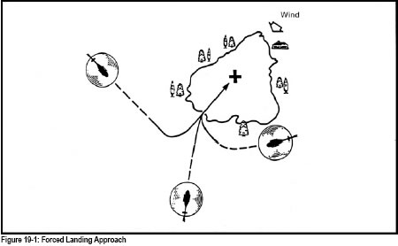
Each time you conduct a simulated engine failure a simulated MAYDAY call should be made. This will gradually become a reflex action, spoken automatically in the event of a real emergency. If time does not permit a full call, even a partial transmission could make the difference in the response of rescue personnel. Your simulated MAYDAY call should contain the following:
MAYDAY Prefix: “MAYDAY, MAYDAY, MAYDAY”
Aircraft Identification: “GABC, GABC, GABC”
Nature of Distress: “Engine Failure”
Intentions: “Autorotating to side of lake”
Present Position: “10 miles north-east of Franz”
Always try to fly as high as the task and common sense allow. This gives much more real estate in which to pick a landing site. Flying low level over obstacles usually results in a forced landing that is difficult to successfully complete.
One significant advantage that an aircraft has over surface transportation is that it is capable of proceeding more or less directly to its destination at a constant and relatively high speed. To use this capability effectively, however, it is essential to be proficient in cross-country navigation. The first stage of this skill is a combination of practical navigation and map reading called pilot navigation. This involves the capability of piloting an aircraft a reasonable distance over relatively unfamiliar territory with a minimum of apprehension and a maximum of pleasure.
You must demonstrate competence in solo cross-country flight in order to be issued a pilot licence, but this will be preceded by dual instruction on all phases of the exercise. The success or failure of a cross-country flight hinges upon the ability to:
The foregoing points are difficult to put into any set order of importance, since changing situations would force a change in that order. For example, when a flight is conducted over terrain or in weather conditions which make map reading extremely difficult, an ability to hold a heading accurately and correctly calculate ETA’S becomes of overriding and vital importance, either in continuing the flight, or diverting to an alternate destination.
The success and enjoyment of a navigation flight depends greatly on systematic preparation and planning. There are several factors to consider which may vary with the conditions under which the flight has to be conducted. The weather, terrain, landing sites, and fuel facilities, together with the availability of en route check-points, may influence decisions and we recommend that you carry out itemized preparation, study, and calculations for the flight, in the following order:
Pilot navigation flights must not be conducted unless VFR weather prevails and is forecast to prevail over the selected route. Therefore, you must obtain adequate weather information. They may be obtained by different means and sources. Be sure to check the actual reports against the forecast weather for aerodromes at which you intend to land and along the selected route. Pay particular attention to the winds. The strength of the wind could play a vital part in your flight planning. Weather conditions are always subject to change; therefore, regardless of meteorological forecasts, in preparing for a cross-country flight, plan the possibility of having to divert to an alternate landing site. This may be done by listing all the suitable alternate landing sites along the route in chronological order on the flight log form. They may also be circled on the navigation chart.
The chart used almost exclusively for pilot navigation is the Transverse Mercator Projection, with a scale of 1:500,000. With this scale, 1 inch on the chart represents 500,000 inches on the ground (approximately 8 miles to the inch). Other scales you may encounter are 1:1,000,000 (approximately 16 miles to the inch) and 1:250,000 approximately 4 miles to the inch). For fine detail, the 1 mile to the inch chart can be used. This chart even shows individual buildings, and is particularly useful for helicopter operations. The 1:500,000 statute mile scale does not exactly correspond to 8 miles to the inch, which is 1:506,880. For short distances the differences may be ignored.
Once you have determined that the weather for a flight will be satisfactory, all pertinent factors must be analyzed and a route decided upon. The most direct route may not be the most desirable; it could be largely over water beyond gliding distance from land, or over a prohibited or danger area. Refuelling stops will play a large part in selecting the route as most helicopters only have fuel for relatively short legs.
In selecting routes, try to avoid those, which include extended periods of flight over areas where map reading is difficult. The ability to read maps is a very important part of pilot navigation. The objective is to get there safely. “As quickly as possible” is an aim that can be sacrificed for this objective.
A checkpoint or pinpoint is a prominent feature or group of features along, or close to the route, used to establish the position of the helicopter. They are also used for other purposes such as in-flight calculation of ground speed and revisions to the ETA.
Main highways, rivers, railroads, and lakes afford excellent and readily identifiable checkpoints for pilot navigation. Take full advantage of them and choose a route, if possible, which will encompass most of them. In the event of any situation that requires diverting from the original flight plan, a pilot strengthens his hand considerably when he knows exactly where he is at the time the diversion must be made.
It is important that the aeronautical chart used is up-to-date and not so dog-eared from use that important details are obscured. Many experienced pilots augment aeronautical charts with information from current automobile road maps, since the latter invariably include more up-to-date secondary roads and highway detail. Remember to use road maps only as a secondary source of information, as distance scales and physical land features are not always displayed accurately.
Once you have selected the appropriate current aeronautical chart(s) and decided on the route, draw the “required track” lines from the point of setting heading through intermediate points to the destination, and determine the true tracks and distances. The required track lines should be drawn in a way that makes them easily distinguished from printed chart detail and yet does not hide chart features. A highlighter pen can be used to emphasize the track line drawn on the chart.
Determine distances, then examine the route carefully and note the following:
To assist in assessing in-flight deviations from track and making corrections, drift lines could be drawn on the chart. These are lines drawn on the chart at 10 degrees each side of the required track line from both the set heading and destination points. They are described in detail later in this text, but can be seen drawn on the chart in Figure 20-1. A preferred set-heading point is an easily identifiable or known landmark, such as a railway or road intersection, a bend in the river, a ATS, a small village or lake, to which the pilot can “eye ball” his way to set heading. Accuracy on setting heading is essential. Setting heading from the downwind leg is not acceptable if the track line originates from the centre of the heliport symbol on the chart, as a half to 1 mile track error could exist from the start.
For rapid distance calculations, the track line drawn on the chart should also be marked into 10 miles intervals (Fig 20-1). Another method is to strike a line across the quarter, mid, and three-quarter waypoints of each track segment. Both these chart-marking systems are to aid mental time, distance, and track error calculations.
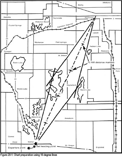
As information relating to the proposed flight is accumulated, enter it in the appropriate sections of a flight planning form. Figure 20-2a shows how the planned flight from Melfort to Humboldt would be entered. The cruise altitude of 4,500 feet, and true airspeed, track, and wind velocity can be entered, and the remaining figures can be added as they are obtained through measurement or calculation. Other pertinent information, particularly weather and landing details, can be added for current and future use.

One of the properties of a Transverse Mercator Projection is that scale can be considered constant all over the chart. Because of this the meridians of longitude, (the vertical lines), converge at a point above the top of the chart, and for that reason a straight line drawn on the chart meets each meridian at a slightly different angle. To offset these differences, place the protractor at the midpoint of the track line when measuring that angle. This is particularly important when the track line is long and runs parallel to the parallels of latitude.
True Airspeed (TAS) is used for navigation computations since indicated Airspeed (IAS) varies with temperature, pressure, and altitude. Conversion of IAS to TAS (or vice-versa) can be done very rapidly on your circular navigation computer. Because most helicopter operations are conducted at relatively low altitude, quite often IAS is used, as the differences are minimal.
In aviation terminology, the term wind velocity, usually abbreviated to W/V, implies both the direction of the wind and its speed. Wind velocities normally change with altitude and, in planning a cross-country flight, this must be taken into account when preparing the flight planning form. Many factors affect the selection of the altitude(s) at which a flight will be conducted and W/V is a major one.
With the W/V selected for the altitudes to be flown, calculate headings, ground speeds and times and then fill out the navigation log (Fig 20-2b). Itemize all tracks, headings, distances, speeds, times, etc., pertinent to the flight. This provides an organized record and schedule for the flight and minimizes the possibility of forgetting important data and having to compute problems in flight. Fuel requirements should be calculated, and while en route these calculations should be checked against actual consumption to determine if the calculated reserves will be available at the destination. There are various forms of flight planning forms and navigation logs, each designed for a particular purpose. Your flight instructor, who will also assist in their preparation, will supply the training organization forms.
The Navigation Log
The helicopter pilot has little time for log keeping in the air (Fig 20-2b), but the following are some of the items that should be recorded, although this may not be possible in most types of helicopter:

It is mandatory that a flight plan or flight itinerary be filed prior to any flight beyond 25 miles of the departure’s point. Among other things, this ensures that the appropriate authorities are alerted should the helicopter become overdue. Air searches can involve considerable time and expense. It is imperative that the pilot closes his flight plan/flight itinerary by notifying the appropriate agency when the intended or alternate destination is reached.
In this text, we do not intend to discuss all the details involved in conducting a pilot navigation flight since the training unit will provide appropriate instruction by means of dual navigation exercises. However, the following are some general points applicable to any cross-country flight.
Magnetic Compass
When you read about vagaries of the compass later in this chapter, you will note that this navigation instrument may be unreliable while the aircraft is being turned, banked, accelerated, or decelerated. Therefore, in order to maintain the all-important heading of an aircraft by means of a magnetic compass, the helicopter must be held straight and at a constant airspeed.
Compass Turns
Compass readings are unreliable when the helicopter is turning. Dependent upon individual aircraft design a turn of more than, or a fraction of, 90 degrees can be estimated by using the angle between the nose of the helicopter and the 9 o’clock and 3 o’clock position as a guide. For example, a turn of 100 degrees to the left can be made by turning on to a reference point which lines up with the 8:30 clock code position.
Heading Indicator
This instrument is subject to the precession errors. The heading indicator must be set manually by the pilot to the magnetic compass and reset about every 15 minutes. It is important to set the heading indicator accurately WHILE IN STRAIGHT FLIGHT.
Altimeter
Atmospheric pressure varies from time to time, and place to place; therefore the pilot must reset the altimeter to compensate for these variations. Current altimeter settings may be obtained on request from control ATSs and Flight Service Stations, or by tuning in to Automatic Terminal Information Service (ATIS) broadcasts.
The generally accepted term to describe navigation by means of a chart is map reading, although the publication used is more correctly called a chart than a map. You will begin to gain experience in map reading during earlier air exercises and learn it progressively, first by identifying highways, railroads, or rivers and relating them to other prominent features on the ground such as towns, airports, power lines, etc. Then, as your ability increases, a specific compass heading should be maintained while reading a chart.
Arrange charts so that both the charts and the controls of the helicopter may be easily managed at the same time. A chart should be folded so that the section being used is readily available, with a minimum of refolding or handling in the air. If more than one chart is to be used, they should be pre-arranged in the order in which they will be required. Align the chart so that the required track on the chart will be parallel to, and pointing in the same direction, as the track being flown.
The recommended practice in navigation by map reading is “from watch to chart to ground”, in other words, noting the time, studying the chart, and anticipating what is to be seen on the ground. There are times, however, such as when you are lost, when the reverse procedure is more valuable, i.e., relating features on the ground to features on the chart. A great deal of practice with both methods is required at varying altitudes and on different headings.
Estimating
To become proficient in pilot navigation, you must develop the ability to estimate. This can only be done through practice and more practice. While in flight, estimate the bearing and distance the helicopter is from a heliport, town or check-point, observe the natural signs of surface winds and estimate their direction and strength; estimate the size of objects on the ground and the distance they are from each other. When passing near a spot that you could consider for an emergency landing, estimate its suitability. Look quickly at a chart and estimate the distance that a certain lake is from the helicopter, what heading will be required to fly to it, and how long it will take to get there.
The more you know about the subject of navigation, the easier and more accurate estimating will be.
Tracking Errors and Corrections
Owing to inaccuracies in the forecast wind and in flying the helicopter, errors often occur that require alterations of heading to bring the helicopter to the destination. Before corrections are discussed, the following terms must be defined:
Ten Degree Drift Lines
In Figure 20-1, 10-degree drift lines are shown opening up from the set-heading point and closing down to the destination. These lines enable the pilot to estimate track errors and required heading changes with reasonable accuracy.
Point A in Figure 20-3 indicates a point on the track made good which is 7 degrees to the left of the required track, indicating an opening angle of 7 degrees. The angle can be estimated more accurately by imagining or physically making a mark at the mid-angle of 5 degrees (line B) and establishing the pinpoint in relation to that mark. Closing angles may be determined in the same manner, using the 10-degree drift lines, which converge on the destination. The angle between the required track and a line joining Point C to destination indicates a closing angle of 4 degrees.
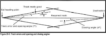

Heading Corrections
Once you have established the position of the aircraft accurately, and provided it is not on the required track, decide upon the best course of action. Normally, approximately 10 to 25 miles should be flown before attempting to estimate any track error, because errors over a short distance are magnified considerably. The heading of the aircraft can be changed so as to either return to the required track, or else fly directly to the destination. This will depend on the position of the aircraft. It is usually more desirable to return to the required track since the route study has been concentrated on that area and, in addition, a line already drawn on a chart is much easier to follow.
Provided the helicopter has not passed the halfway point, the double track error method or the visual alteration method can be used. If the helicopter is beyond the halfway point, you can still use the visual alteration method, or alternatively, the opening and closing angle method. Each method will be discussed in detail later in this text but first some basic geometry may help.
The key to understanding how these various methods work lies in the fact that if the helicopter heading is altered in the direction of the required track by a number of degrees equal to the track error or opening angle, the resulting heading will produce a track parallel to the required track. The desirable thing now is to get us back over track so that we can fly that heading. Some orderly method must be followed to take the aircraft from its present position off track to a point on the required track. Once this is accomplished we can then take up and fly the new corrected heading. Alternatively, we have the chance of flying direct from the position off track to the destination.
Using the 10-degree drift lines in Figure 20-4, it can be seen that the track made good is widening from the required track by an angle of 7 degrees. By altering the heading 7 degrees to the right, we now have the heading that produces a track parallel to the required track and is approximately the heading to steer when the required track is regained. (This is not strictly true, because in either method mentioned below the new heading calculated to keep the helicopter over track may not be exactly correct, due to the fact that the direction of the wind relative to the new heading is altered and drift may remain what it was before. Yet for most practical purposes the change of drift caused by such a small alteration in heading can be neglected.)
If you decide to return to the required track, the primary method is the double track error method. Simply double the amount of track error or opening angle, and apply this to the original heading in the direction of the required track: the helicopter will regain track in approximately the same period of time as it took to drift off track, and the required track will be intercepted again at a distance along track equal to twice the distance from the set heading point to the point when the heading change was made (Point A in Fig 20-3). On regaining track it is necessary to subtract half the correction applied to the original heading to obtain the heading to keep the aircraft on the required track.
If a positively identified landmark on the required track can be seen, the visual alteration method can be used. Once again the key fact is the heading change that would produce a track parallel to the required track. After determining the opening angle and applying it to the heading that produced the error, we now have a heading that we can fly once we are back on the required track. By simply flying visually from the present position (A in Fig 20-4) to the positively identified landmark, the new heading can now be flown and the helicopter should remain on the required track.
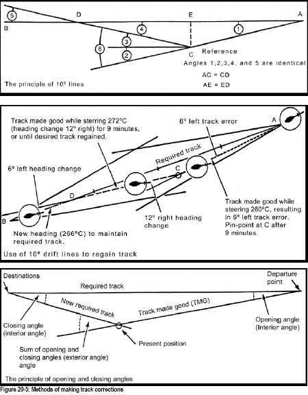
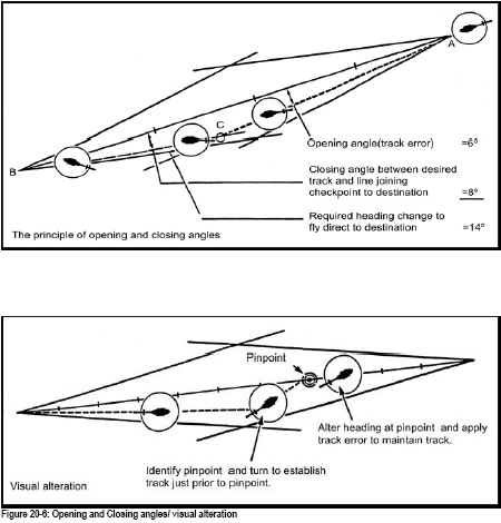
Now let’s look at a practical example of these two methods in Figure 20-7.
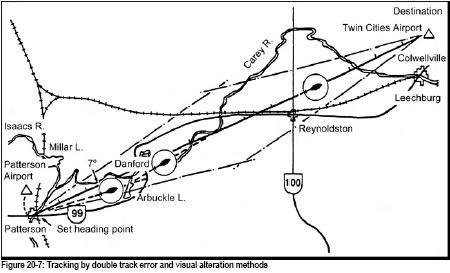
We take off from Patterson Airport and set heading at 16:00 Z over the point where the railway line crosses the Isaacs River, at the town of Patterson. Our calculations have indicated that we must steer a compass heading of 065 degrees on our trip to Twin Cities Airport, 148 miles distant. After 14 minutes (16:14 Z) we pinpoint ourselves at the north end of Arbuckle Lake, and using the 10 degree drift lines determine that we are 7 degrees to right of track. A heading change of 7 degrees (058 degrees) left would result in a heading whereby we would parallel the required track. But as we wish to regain track using the double track error method, we alter heading to 051 degrees (065 degrees - 14 degrees = 051 degrees). This new heading is held for an additional 14 minutes and we regain track just south of the bend in the Carey River at 16:28 Z. At this time we alter heading 7 degrees right and steer 058 degrees. Any physical features near or along the track line, which will confirm that the track has been regained, will be helpful, but if none are available, the heading should be altered at the calculated time. Revised ETA can be made while flying towards the required track. If we had decided to use the visual alteration method, we could have flown visually to Danford, which is right on track and easily identifiable, and then steered 058 degrees (065 - 7 = 058) which should keep the helicopter on track.
Some flights are carried out over featureless terrain and may be more than half completed before a reliable pinpoint is located. This is where the opening and closing method can be used, or again the visual alteration method. As we have already discussed the visual alteration method, let’s have a look at the principle behind the opening and closing method. Go back a few pages and study the definitions of opening angle and closing angle. By going back to basic geometry again and consulting Figure 20-5, it can be seen that by altering the heading by an amount equal to the sum of the opening and closing angles, we should track to destination.
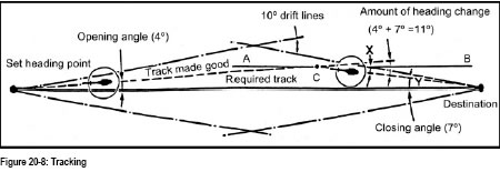
In Figure 20-8 the line A-B passes through Point C where the heading change is made, and is parallel to the required track. At Point C, which is 4 degrees to left of track, a 4-degree right heading change would parallel the track. Angle X equals Angle Y (the closing angle) and using the 10 degrees drift lines we can determine that Angle Y equals 7 degrees. Therefore at Point C, an 11-degree right heading change (4 degrees + 7 degrees = 11 degrees) should permit the aircraft to track directly to destination.
Now let’s look at a practical application. In Figure 20-9 the calculated heading to fly from Leech Airport to Carnegie Airport was found to be 105 degrees compass.
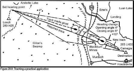
Set heading time was 15:00 Z. No reliable pinpoint was available until 45 minutes later, close to where the north-south railway crosses Highway 10, 82 miles along the track. Using the 10-degree drift lines we find the opening angle to be 4 degrees and the closing angle to be 6 degrees. Therefore, in order to fly direct to Carnegie Airport, a 10-degree right heading change (4 degrees + 6 degrees = 10 degrees) leads onto a heading of 115 degrees (105 + 10 degrees). As the ground speed is found to be 109 knots and there are 49 miles left to go, the revised ETA would be 16:12 Z. It should be understood at this time that the opening and closing method can be employed at any distance along the required track, and is not limited to use after passing the halfway point. Alternatively, a visual correction could have been made to the point where the original required track meets the curve in the railway line at Blackburn Mines, where a heading of 109 degrees (105 degrees + 4 degrees opening angle) taken at the time would have kept the helicopter on the track to Carnegie.
The Drift Compensation Method
Experienced pilots often establish heading by constantly compensating for drift as the flight progresses. When the heading to maintain a desired track is established by this method, drift angle can then be easily computed if you need it. Visibility must be such that enough checkpoints are visible to maintain an accurate track.
Select at least two prominent check-points a sufficient distance apart ( 5 to 10 miles or more, depending on the terrain), on the desired track ahead of the helicopter. Maintain a heading which keeps the nearer checkpoint aligned with the farther one. When the helicopter and the check-points remain on the same line, the heading indicated on the compass will be the heading which, provided there is no wind change, should keep the helicopter on the track required for the remainder of the flight. To continually compensate for wind effect, select another checkpoint on track in the distance before the nearer checkpoint is reached; then repeat the alignment and drift compensation procedure. Calculate ground speed by time and distance between checkpoints to keep ETA accurate.
Setting Heading
After takeoff, establish the helicopter on the desired compass heading for the first leg, either over the heliport or over a convenient prominent checkpoint. Note the time and enter it in the flight log and calculate the ETA for the destination and the first checkpoint. Remember, to ensure accuracy in determining the actual amount of drift, it is necessary to begin the navigation exercise directly over the planned set-heading point. Immediately after you are established on the first heading, check the chart and pinpoints on the ground to confirm that the aircraft is in fact heading in the correct direction.
It is important to bear in mind that the objective of the pilot navigation cross-country exercise is to practise navigation by maintaining accurate headings, calculating and making corrections for drift, and calculating accurate ETA. Accurate map reading for exact determination of aircraft position is essential to provide the necessary information for calculation of heading and ETA corrections when required.
En route
Provided the set-heading procedure is properly completed, you can then concentrate on accurate flying, identifying checkpoints, and maintaining a good lookout. A prior knowledge of ETA over checkpoints along the route will allow you to anticipate and thereby identify them easily as the flight progresses. However, look out for other traffic must not be sacrificed to the navigation of the helicopter. Also perform normal in-flight checks at the prescribed intervals.
ETA Revisions
At the first positive pinpoint, ideally between 10 and 25 miles from the departure point, the ground speed should be calculated and ETA revised if necessary. Rely on the navigation instruments in the aircraft, rather than inexperienced personal judgement. It is most important to maintain a steady planned heading and airspeed. If you cannot at once recognize the track being made, do not suspect the compass of unreliable behaviour; continue to hold a steady heading until you reach a recognizable checkpoint. If a heading indicator is being used, check its heading frequently with the magnetic compass and reset it as necessary.
Checkpoints and Pinpoints
Time is one of the essentials of navigation, so acquire the habit of calculating ETA for en route checkpoints. This will help locate checkpoints by preventing the habit of looking for specific places on the ground too soon or too late. It is imperative that a reliable watch or clock be on board the helicopter during cross-country flights. The number of pinpoints on a leg varies according to the length of the leg. Usually one pinpoint every 10 minutes is sufficient, but more may be used if necessary. Once the aircraft has passed the pinpoint, immediately begin to anticipate the next checkpoint in the same manner as the previous one was anticipated.
Do not fly a zigzag path from check-point to check-point when the checkpoints can be readily identified from a position on or near the required track. There is no disgrace in not arriving directly over a check or turning point. Alteration in heading should be deliberate and aimed at flying in as straight a line as possible.
One of the skills required of the helicopter pilot is the ability to rapidly estimate a new heading to an alternate destination when, for various reasons, continuation of the flight is impracticable. Computation of headings, speeds, distances, and ETA in flight involves the same basic procedures as those used in pre-flight planning. However, because of space and time limitations and having to fly the helicopter simultaneously with computations, the pilot must take advantage of all possible short cuts. It is rarely practical to actually plot a line on a chart and mark checkpoints and distances as in pre-flight planning.
With a little practice, headings to alternates can be determined quickly with reasonable accuracy, by interpolation and mental transposition of airways and air routes on the chart or the azimuth information on the compass rose encircling VOR stations. These all have the advantage of already containing the magnetic variation for the general area. Use a pencil or the hand (on edge) as a straight edge. If airways or a compass rose are not close enough on the chart to be used, an angle may be estimated as being a fraction of the 90-degree angle between the meridians of longitude and parallels of latitude found on the chart. If possible, draw a line freehand on the chart from the divert point to the alternate destination.
Distances can be estimated accurately enough for diversion purposes by using the thumb and index finger as “dividers” applied against the scale on the chart, or easier still, against the mileage lines that were marked along the original track before the flight began. The compass rose circles around VOR stations are all 35 statute (30 nautical) miles approximately in diameter on Canadian 1:500,000 aeronautical charts.
When diversion to an alternate destination becomes necessary, the decision to change to a new heading should be made as early as possible. First, consider the distances to all available and suitable alternates, select the one most appropriate and then estimate the heading to the alternate chosen. Turn the aircraft to the new heading and then, more accurately, estimate drift correction, distance, speed, compass heading, and ETA while proceeding towards the alternate. Under the circumstances, it may be advantageous to “hold” over a known checkpoint while computations are made.
If a suitable choice is available, always divert to the spot that offers the easiest route to follow, such as a highway, river, power line, etc. This is particularly important if visibility is a factor. If low-level navigation is required due to low ceilings keep a careful lookout for obstructions. Diversion is often synonymous with emergency; this is not time to test your pure navigation skills if you don’t have to.
To compensate for the wind, which can often be an unknown factor in diverting to an unplanned alternate, establishing a heading by means of drift compensation may be the best expedient. The forward landmarks should be readily identifiable and, if visibility is a factor, they should also be reasonably close to the desired track. Again, rely on the instrument indications and any new heading established by drift compensation will be fairly close to the heading originally estimated for the diversion track.
Mental arithmetic can be sometimes difficult when flying, and you may add to the following suggestions as your experience increases. When the distance and time is known, finding the ground speed is much easier if the “time” part is a fraction of 60 minutes. 25 NM covered in 12 minutes is 125 kts. We know that 12 minutes multiplied by 5 equals 60; thus, by multiplying the distance covered by 5, the ground speed can be easily determined. Another example is: 40 NM covered in 20 minutes is 120 kts (40 x 3). If a distance marker on a track line coincides with a checkpoint, the time at the distance marker twice the distance away will be twice the elapsed time.
If You Are Uncertain of Your Position
The danger of jumping to the wrong conclusion is very real when you cannot recognize expected landmarks. There are times when you will be uncertain of your position. Such moments require calm reasoning and a recognized procedure. The recognized procedure is as follows:
Usually you can establish your position within a short time and continue the flight. You must never assume, however, that you are in a certain position. Check for a possible shift in the wind by drawing a circle of uncertainty.
To do this, draw a circle on the chart around the position you would be in if you were on track and on time. The radius of the circle should be 10 per cent of the estimated distance flown since the last confirmed position. Checks within the circle of uncertainty for any prominent physical features you have noted on the ground, and when you have positively identified one or more landmarks, fix your position. Remember, positive identification of a distinctive landmark is the only way to get back on track. If you decide that you are definitely lost, LAND. Do not exhaust your fuel in aimless wandering from one heading to another trying to pick up a landmark. You can usually find a landing spot, you burn a lot less fuel, and tend to think a lot more calmly and rationally when you are sitting on the ground. Always work to plan. Notify ATC by radio that you are lost, or try to contact any other aircraft or control agency. When you have established radio contact, transmit your general position, the amount of fuel remaining in the tanks, ask for whatever assistance you need, and indicate the action you propose to take.
Usually you will have a rough idea of the direction of home base and can turn towards it, while continuing to search for prominent landmarks. “DF steers” are available from ATC in many areas and provided you are within radio range a heading to fly will be freely offered. Do not be too proud or afraid to ask for assistance.
If you have no idea of the direction to fly, set up a triangular pattern at endurance speed settings, at the highest practical altitude, to alert the radar network. If shortage of fuel becomes a problem, land to conserve remaining fuel.
In an extreme emergency, if there is absolutely nowhere to land, you should broadcast a MAYDAY distress message on 121.5 MHz giving the helicopter type, the nature of the emergency, the amount of fuel left, the assistance required, and your immediate intentions. Listen out on the same frequency for instructions.
One advantage of the helicopter over other aircraft is its ability to land in unimproved locations. Do not exhaust your fuel supply by continuing to fly; select a suitable field near habitation if possible, and land preserving sufficient fuel to return to base. A thorough map study on the ground may re-orientate you, but do not take off again if you are still unable to positively fix your location.
For one reason or another, such as a diversion to an alternate, it may be necessary to calculate a track to take you over the route you have just flown. An easy method for mentally calculating the reciprocal of a heading is to add 200 to headings less than 180 degrees and then subtract 20. For headings of more than 180 degrees subtract 200 and then add 20.
Once on the reciprocal track, the allowance for wind will be opposite to that used outbound. If 10 degrees was added to the outbound track to allow for drift, it will now be subtracted from the reciprocal track to obtain a compass heading. This heading should be adequate until a new and more accurate one is calculated. Turn the chart 180 degrees, map read back to a known fix, and then resume normal navigation either back to the point of departure or to an alternate destination.
There may be an occasion, during a cross-country flight, that will necessitate low-level navigation. Some of the flying on your flight test may also be done at low level. Special mention is therefore made now of low-level map reading.
The greatest difference in navigating at cross-country altitudes lower than usual is the restricted field of view at low level, which becomes extremely limited when flying over rough or hilly terrain. This, combined with the greater attention that must be given to handling the helicopter, cuts down the time you have to positively identify your landmarks and checkpoints as they come up. Since you cannot hope to continually compare your checkpoints with the chart to assist identification, you must pick unique, easily recognizable features. Line features, such as railway lines or roads, that run 90 degrees to the track are used as check-points, and those that run to the turning point are used as lead-in lines.
During low-level navigation flight, you have to be on the lookout for obstacles such as TV and radio antennas, power lines, factory chimneys, and sharply rising ground. The set-heading procedure should be carried out if possible, before descending to the low-level altitude, and navigation should be strictly confined to map reading. Log keeping is impossible because of the urgent need to keep a good lookout. Check outside frequently if altitude is critical, to avoid flying into the ground. If you become uncertain of your position, if possible climb as high as necessary to give yourself an extended field of view and try to identify a landmark.
Remember that when you are doing cockpit checks you must not bury your head in the cockpit. Complete the first item and then pause to have a thorough look around; complete the next item and look around again; continue in this way until the check has been fully covered. If your low-level navigation technique is to be a success, you must develop good handling habits, so that most of your time can be devoted to checking your position and to look out.
Under some conditions of flight, this instrument can react in wild motion.
The mechanical and other reasons for the eccentric behaviour of this instrument will not be discussed here. What is important to know at this time is that the magnetic compass can be relied on only when the helicopter is flying straight, and at a constant airspeed.
When a helicopter on a northerly heading executes a turn, the compass card remains stationary on its pivot or momentarily turns in the opposite direction. This falsely indicates less than the real amount of turn. The compass may be said to lag in turns from a northerly heading.
When a helicopter on a southerly heading executes a turn, the compass card turns faster than the helicopter, instead of remaining stationary on its pivot. This falsely indicates more than the real amount of turn. The compass may be said to lead in turns from a southerly heading.
When a helicopter is maintaining an easterly or westerly heading, changes of speed will cause the compass to falsely indicate a turn, deceleration will indicate a turn to the south and acceleration will indicate a turn to the north.
Weather conditions should be constantly observed during a cross-country flight. Any sign of deteriorating weather must be seriously assessed and appropriate action taken without delay to keep well clear of it. When you encounter or are about to encounter bad weather, avoid haphazard changes of heading looking for a path through it, as this may disorient you. The navigation exercise then breaks down into a confused search for a way out of the weather. If any doubt exists concerning the weather ahead, to avoid it and keep the navigation of the helicopter intact, turn the helicopter completely around and fly the reciprocal of the original required track. Do this by making a standard rate turn through 180 degrees, which should take one minute if the turn is being timed.
Remember that you are flying a helicopter. Unless you are over extremely inhospitable terrain you can normally find a suitable area and land until the weather moderates.
Pilot navigation requires the application of common sense. For example, such things as the sun, rivers, lakes, the location of prominent landmarks, etc can verify approximate direction. When en route, communicate briefly with as many ground stations as reasonably possible. It is sound practise to let flight progress be known and it is always good insurance to have the current weather for the destination and intermediate points, which may be provided by some ground stations. When the flight is apparently going well, do not be lulled into a sense of false security and abandon map reading for long intervals. Continually take mental note of areas on the route that would be suitable for emergency landings. Should something occur which appears to affect the safety of the flight, evaluate the situation carefully; the most prudent action may be to land at the first opportunity.
Do not hold charts or other pilot navigation material too near open windows, as there is a strong suction at such points that can easily snatch light articles out of a helicopter in flight. At last, make sure that more than one pen or pencil is available.
“A helicopter is operating low level in restricted visibility; the pilot has reduced speed to 60 mph because of the weather. While flying in a narrow valley, high tension cables appear rapidly out of the gloom.” This situation is an all too-often occurrence, so what can you do? Correct! — a rapid deceleration, or quick stop, as it is sometimes called. The above example is one use for a quick stop; another is as a means for developing co-ordination and accuracy.
The purpose of a rapid deceleration is to stop the aircraft rapidly. There are two main variations: the into-wind and the downwind stop, obviously if you are crosswind a partial turn into wind is utilized. The downwind or 180° emergency turn entails turning the helicopter back into the wind during the stop, avoiding the dangers of a low airspeed while facing downwind.
Fly the helicopter straight and level, at 70mph and 50 feet AGL, as you run in choose a heading reference in the distance (Fig 21-1). Give a verbal warning “Practice quick stop, go”, on the executive word “go” proceed as follows:
The gentle flare is to help you to become proficient at the exercise and smooth coordination of the controls. Once you have mastered it, the manoeuvre can be speeded up to achieve the necessary stopping distance. The larger the flare, the greater will be the tendency to climb, leading to larger control movements overall and greater difficulties with control coordination.
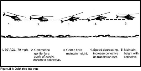
Your instructor will show you that if you flare too harshly the needles could split, and how to recover from this situation. Be sure to anticipate with collective before losing translational lift, to stop any tendency to sink, otherwise you could be setting up the conditions necessary for vortex ring.
Fly the helicopter straight and level, at 70 mph airspeed, 50 feet AGL.
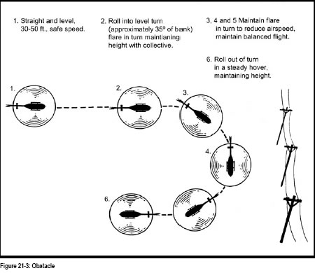
The handling of the helicopter should be with small, smooth control movements, as this exercise requires a high degree of coordination and accuracy.
The helicopter is a very versatile machine. Because of this, it is called upon to do many varied tasks. More and more uses are being found, and as the number of tasks increases, the number involving low level operations increases. The following examples are all flown low level: pipeline, hydro-line, beaver, moose and deer survey. There are numerous other jobs, most are of the reconnaissance variety and all are very demanding because of proximity of the ground and the dangers associated with flying close to the ground.
A. Navigation.
As you have no doubt discovered in practising cross-country techniques, the lower you fly, the harder it is to map read because of the reduced area visible and the shorter time available for identifying landmarks. To try and navigate a straight line is virtually impossible because of hills or obstacles on your track.
1. Wires: While flying low level your lookout cannot be relaxed for more than an instant, as many of these lines are extremely difficult to see, especially across valleys and in differing light conditions.
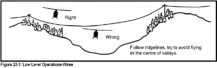
If you are about to fly low level with someone else on board brief him or her to say “Wires” as soon as they are seen. The pilot-in-command should reply either “Contact” or “No Contact” to confirm the sighting. Similarly, the pilot should comply with the above rule.
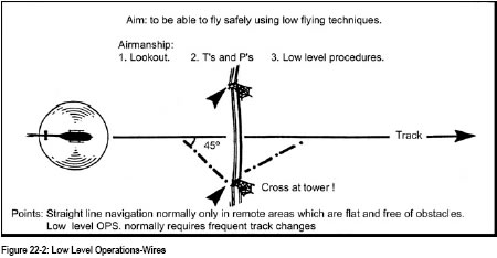
Wire lines should be crossed at an angle of 45 degrees to give the pilot a choice of turning away from the line or going over the line in case of emergency.
2. Minimum altitudes and distances: Built-up areas and livestock are to be avoided when flying low level. In most cases, flying over these sensitive areas are illegal and dangerous.
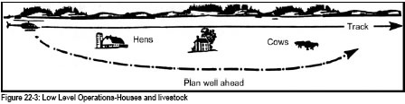
3. Low-level flight over the trees: they give little or no choice for you to make an emergency landing. If there are clear areas, try to choose the best flight path with regard to your route
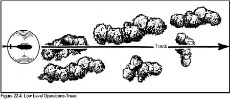
4. High ground: Rising or high ground can also cause you to deviate from your track. Try when flying towards high ground to approach at an angle of less that 90 degrees, turning away should be easier in the event of emergency.
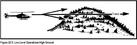
B. High Winds.
C. Communications.
Radio performance deteriorates the lower you fly, particularly line of sight systems including navigation aids.
D. Emergencies.
Your instructor will show you the techniques to employ should an emergency occur at low level. Be aware of the «avoid» areas of the Height Velocity chart.
Usually low-level flying is not practised solo. All flying organizations have rules that must be adhered to with regard to height and suitability of local training areas.
Helicopters are often called upon to land on unprepared, sloping terrain; indeed it is sometimes very difficult to determine the existence of a slope until the moment of landing. Therefore, as a helicopter pilot, you must be capable of landing your aircraft on terrain that is sloping or has a doubtful surface. The techniques you will learn in this lesson are also suitable for use when faced with a landing on muskeg, packed snow, or any uncertain surface.
Prior to commencing your landing, ensure that you have made a good reconnaissance of the area for obstacles that could pose a hazard to the tail rotor as you manoeuvre, or that could snag the skids and cause a rollover accident. You must also carefully consider the wind velocity, as this may be a limiting factor in the conduct of the manoeuvre. For example, it might be very difficult or sometime dangerous to carry out slope landings with the tail pointing into wind because of control difficulties. Prior to commencing this exercise, you must also review the helicopter flight manual limitations section, as most light helicopters have maximum allowable slope landing limits published. However, lateral slope of 5 or 6 degrees is considered acceptable for most of helicopters.
Sloping ground operations can be divided into four phases as follows:
During any landing or takeoff, the pilot makes a reconnaissance of the area. Should the chosen area likely have a soft or slippery surface, or if obstacles exist, then extra care must be taken to ensure that landings and takeoffs can be conducted safely. This is also the case with sloping ground.
Remember that the helicopter hangs one skid low in a steady hover. You can use this information to determine which skid to place uphill, as it will be easier to land on the slope in this manner. Your ability to conduct cross-slope landings will also be determined by cyclic limitations; there may be insufficient cyclic travel available to you to land the helicopter.
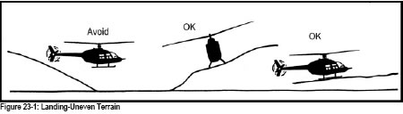
It is desirable to land into the wind whenever possible, but there will be times when you have to compromise on the wind direction. Similarly, you may have to compromise on the slope of the ground to carry out the landing. It is very important to make a thorough reconnaissance of the selected area before you attempt the landing.
During sloping ground operations, the tail rotor is extremely vulnerable. You must remember that the tail rotor is some distance behind you, and care must be exercised when manoeuvring to ensure that you do not strike the tail rotor on any obstacles, or the slope itself. This is especially so when performing hovering turns and when landing either upslope or downslope. When you are required to turn in close proximity to the slope, always turn the tail away from the slope. Using this procedure will lessen the chance of a tail rotor strike.
In preparation for the landing you must establish a steady hover over the selected spot (Figure 23-2). Gently begin to lower the collective, allowing the helicopter to settle until the uphill skid contacts the slope. Pause slightly. Now as you further lower the collective, you must also progressively move the cyclic towards the slope keeping the rotor-disc parallel to the horizon. This will prevent the helicopter from sliding down the slope. It is possible to exceed the limits of cyclic travel at this point, or you may find that the helicopter begins to slide. Should this occur, smoothly lift the helicopter into a hover clear of the slope and select another landing spot. If sufficient cyclic control remains, continue to lower the collective until the downslope skid contacts the ground. Throughout the landing manoeuvre, ensure that you prevent yaw with use of pedals. Once on the ground, carry out a “seating check” by making small and gentle movements of both pedals and collective. Do not centre the cyclic, or roll back the throttle, until you have performed the seating check and you are satisfied that the helicopter is not going to slide. Under some conditions (e.g. dropping off passengers and leaving) it may not be desirable to centre the cyclic or carry out the seating check, nor roll back the throttle.
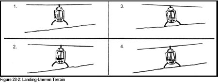
It is most important that your control movements are smooth and accurate, and that you avoid any tendency to over control as it is possible to set up a roll rate, especially about the skid in contact with the slope, which could then lead to dynamic rollover that opposite cyclic could not counteract.
In preparation for the takeoff, carry out the pre-takeoff checks, and ensure that the rotor RPM is correctly set. Before beginning to gently raise the collective, level the rotor-disc, so that it is once again parallel to the horizon. The downslope skid will begin to rise; in the reverse of the landing sequence (fig 23-2), the cyclic must now be progressively moved away from the slope as the collective is being raised. Coordinate the movements of the two controls, so that the helicopter smoothly breaks contact with the ground and rises vertically into the air. Maintain direction with the pedals and ensure that all lateral movement is eliminated, avoiding the possibility of a dynamic rollover situation.
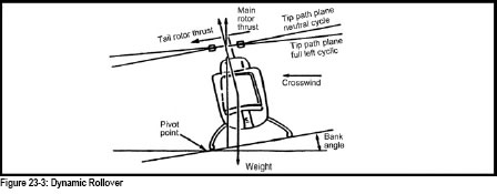
Your instructor will review with you the conditions that could lead to dynamic rollover and the avoidance techniques. It is important that your helicopter has been properly loaded and is within CG limits, both laterally and longitudinally, as an out-of-limits helicopter could lead to a situation favourable to dynamic rollover. For similar reasons, the importance of smooth, gentle control movements while ensuring that the skids are clear of snags and obstacles, and the importance of maintaining RPM at maximum will be stressed.
It is possible to exceed the cyclic control limits when performing slope landings. When moving the cyclic towards the slope you may:
Do not continue to attempt to land under these circumstances, but lift off again to the hover.
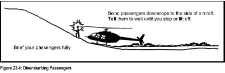
Your instructor will discuss with you the potential hazards of embarking or disembarking passengers while the helicopter is on a slope. The rotor blades are very close to the ground on the uphill side and present a real hazard to passengers. Brief your passengers of the direction to take and remain within your view the whole time.
The techniques in this section are usually employed because of operational situations and conditions. A good rule of thumb is to only employ them when necessary.
There will be many occasions where operational considerations, such as high all-up weight, high-density altitude and unfavourable wind conditions or obstacles, dictate the use of advanced techniques. The techniques learned in Exercise 09 and 12 should still continue to be used in normal conditions. When you practise these new skills, it is important to keep a good lookout for obstacles and be sure that the limitations in the Flight Manual are not exceeded.
The no-hover takeoff can be usefully employed in conditions where snow, dust, ash, sand or debris may cause a hazard if normal techniques are used (Figure 24-1).
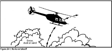
As this type of takeoff is not preceded by a hover-check, you have to be sure that the helicopter weight and balance are within limits, and that sufficient power is available for the intended departure.
This type of departure is economical in power required, since it involves making maximum use of the ground effect until translational lift is acquired (Figure 24-2). However, a relatively flat area, free of obstacles, is required for this technique. It is useful if the helicopter is heavily loaded and it is not possible to perform an into-wind transition.
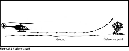
It is most important to use gentle and smooth control movements to get the maximum benefit from this type of takeoff. The take-off profile is extremely flat initially, so it is essential to look out and keep a close watch on the ground to maintain a safe clearance.
This type of takeoff is employed when there are obstacles in the take-off path but the area does not require a vertical ascent. More power will be required but you should use only the amount that is necessary to successfully depart over the obstacle. A good method to ensure obstacle clearance is to maintain the same relative vertical distance between the obstacle and the rotor disc, as viewed from the cockpit.
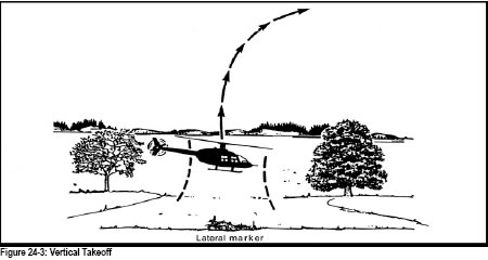
This technique is used when there is insufficient space in the area to perform the methods previously described. The conditions and obstacle height will dictate the power required but much higher power settings are normally the case (Figure 24-3).
When using this technique, be careful to set a low rate of climb, especially when heavily loaded, because as you lose ground effect you could stop climbing and have to descend. If you use a large amount of collective for a high rate of climb, you need a large amount to stop the helicopter descending and overcome inertia built up on the way down. This could lead to exceed aircraft limitations.
This type of landing is used when it is undesirable to approach to the hover, generally because of snow, dust or ash. It should also be noted that it requires less power than a normal approach and could be utilized in situations where power requirements are high, e.g. heavy loads, hot and high altitude operations:
The surface of the selected spot requires a good reconnaissance to confirm its suitability for this type of landing.
This type of landing is similar to a No-Hover except it requires less power, but a flat, smooth surface is essential, preferably cleared with a reliable reconnaissance:
One of the helicopter’s most often used capabilities is that of being able to operate in relatively unimproved locations, and to land and take off from confined areas (Figure 25-1) which may be bordered by buildings, high trees or other obstacles. It is essential that the helicopter pilot learn how to operate the helicopter safely in this environment and be able to take full advantage of this unique ability.
You may consider this exercise in seven steps as follows:
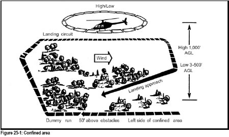
Once again the height and airspeed that you fly this reconnaissance will vary according to helicopter type. You must be able to see well enough to make an accurate assessment of the approach track and the landing area. The height will vary between 300 and 500 feet AGL above the nearest obstacles or obstructions. Keep the area on your side of the helicopter during this reconnaissance. After descending from the high reconnaissance check the wind to confirm its direction and strength. Nearby smoke, small ripples on water, long grass, flags or tree leaves are good wind indicators. Quite often in strong winds the approach must be adapted to ensure landing into wind. On other occasions, it may be necessary to accept a crosswind, or in light conditions it may even be able to ignore the wind.
To effectively carry out the low reconnaissance, you must be at a height to see well enough to make an accurate evaluation of the approach and departure paths and the landing area. You should select the maximum height that will still allow you to make this judgement. Generally you will find that between 300 and 500 feet above the obstacles will be suitable. Too low and you may lose sight of the landing area; too high and you will be unable to discern details which may determine if the area is suitable.
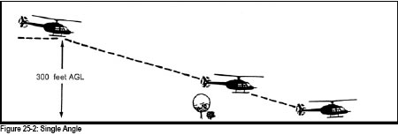
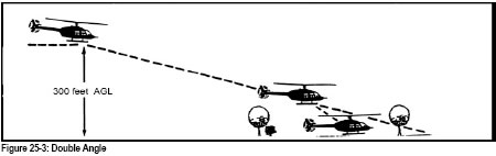
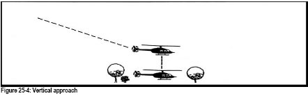
Confined area training begins in relatively large areas that allows for normal approaches and departures, and also allows manoeuvring of the helicopter within the area. Once comfortable in this environment, you will advance to more restricted sites that require steeper approaches, and their size limit your ability to manoeuvre the helicopter. Out of wind approaches are practised, as the shape of the area or the surrounding obstacles often demands them.
NOTE: There is a great need to exercise your common sense in this exercise. The easiest way is normally the best way generally holds true for confined area work.
If the helicopter pilot chooses a flight path, airspeed and a rate of descent that coincides with the aircraft’s downwash, the helicopter could enter a condition known as the Vortex Ring state. The stall condition formed by the rate of descent flow in opposition to the induced flow, combines with the tip vortices present in all regimes of flight to produce a turbulent rotational flow on the blades and an unsteady spanwise shifting of that flow. This condition induces a very rapid rate of descent, vibrations, excessive flapping and a reduction in cyclic authority that could result in an accident. Obviously, this condition is to be avoided and the helicopter pilot should be able to recognize the incipient stage and be able to affect a safe recovery.
Your instructor will review the causes, conditions and symptoms of vortex ring. During a steep approach, at a high gross weight, high-density altitude and in a downwind or light wind condition; the helicopter may enter its own downwash and the development of vortex ring state. This situation would certainly contribute to the onset of vortex ring, but not necessarily cause it. The phenomenon is most likely to occur when all the conditions listed below are present:
Almost every transition from forward flight to a hover utilizes a powered approach, a rate of descent and a reduced airspeed. To prevent the occurrence of vortex ring, control your rate of descent less than 300 feet per minute.
Recovery Techniques. There are two methods of effective recovery from the vortex ring state. Both change the airflow conditions causing it and both involve a loss of height:
You should note that an increase in collective alone may not result in a recovery and indeed may only serve to increase the rate of descent. This increase in blade pitch will cause the vortices to intensify in strength and will result in a more rapid descent.
There are some uninformed pilots who use “settling with power” to describe vortex ring, in fact some publications use the terms interchangeably. Confusion results when symptoms are related that do not describe true vortex ring but rather describe “settling with insufficient power”. This may occur when a pilot attempts to arrest a rapid, low power descent only to find that he has insufficient power available to bring the helicopter to either a hover or a no-hover landing without exceeding the engine limits. However, this is not a vortex ring situation.
Another situation, ‘over-pitching’ is often misinterpreted as vortex ring. This is where the pilot rapidly increases collective considerably and the engine cannot produce enough power to overcome the large, swift increase in drag on the rotor system. The result is that the rotor system quickly slows down and loses efficiency causing the helicopter instantly to sink. Again, this is not vortex ring.
The most common situations, where you would be most likely to encounter vortex ring, are usually when you misjudge the wind with a heavy load on a hot day. Downwind approaches to a confined area, or a mountain pad, are two good examples. Always control your rate of descent carefully on these occasions, and make sure an escape route is available. Your instructor will discuss the symptoms and recovery techniques more fully. Demonstration of this exercise is not generally performed, as the stresses on the airframe and rotor system are unknown.
PREVENTION IS BETTER THAN CURE.
Loading and maximum weight operations are shown here to be one particular exercise. Realistically, you will be gaining experience in this exercise almost from the day you start your course. To operate a helicopter to its full capabilities, a thorough understanding of its limitations is required. All helicopters have definite limitations with regard to both weight and balance.
It is the responsibility of the pilot-in-command to load the helicopter within the limitations set out in the authorized weight and balance section of the flight manual. To simplify loading problems, manufacturers supply pre-calculated graphs, charts and loading examples. You will be shown how to calculate the weight and balance for your type of helicopter.
In normal working conditions, because your loads are frequently varied, you should be familiar with the effects of these variations. A check of weight and balance should be included among the factors considered by the pilot in his pre-takeoff checks. If in any doubt, always calculate with either the charts, or reports, before attempting the load. Always perform a hover-check; this will give you an accurate check of the power being used, and therefore what is still available to you, and how the load is affecting your centre of gravity.
You will be shown how to estimate the power required for different situations. The hover-check is really the accurate way to practically find the power required and permit you to evaluate the power available on that particular flight. Remember that a few degrees in temperature and/or
a change in altitude can make noticeable changes in the performance of your helicopter.
You will be shown how to maximize the space available with varied loads on the particular type you are flying. This will include all baggage compartments and litters in addition to the cabin. You must secure all loads utilising straps, nets, or any restraining device available. As some loads may be classed as dangerous goods, check in the company operations manual to determine how to handle them before you commit to loading them in the aircraft. Unloading is as important as loading. If you are carrying loads to several destinations, arrange them for ease of delivery, but be sure to arrange them so as to have as little effect on weight and balance as possible. Always perform your hover-check after each stop. Sling loads are dealt with in Exercise 28.
The pilot-in-command is responsible for briefing any passengers carried on board the aircraft. Passengers have to be shown how to embark and disembark safely, the use of seat belts, procedures to be used in the event of emergency, including exits, and policy on smoking whilst in the helicopter. Most helicopter company operations manuals have a safety-briefing checklist included in them to ensure nothing is forgotten. Always use it if available.
In conclusion, use your common sense when you are working. Remember that increasing your weight, altitude or both, affects performance not only in powered flight but also in autorotation.
One of the features of the helicopter, which sets it aside from other aircraft, is the ability to transport many different types of loads suspended from a cargo hook. This unique transportation method allows the helicopter to deliver cargo where even it cannot land, and to perform highly specialized tasks such as water bucketing, logging, and aerial construction. It is essential that to carry out safe slinging operations, the pilot and ground personnel involved be thoroughly conversant with the techniques required.
For the purpose of this exercise and indeed, for any slinging that you do operationally, carefully select the routes that you will fly to ensure that you do not overfly built-up areas to minimize the danger to persons or property. Your instructor will review with you Sections 602.16 and 602.23 of the Canadian Aviation Regulations prior to the conduct of this exercise.
Prior to conducting any slinging operations you should carry out the following checks in addition to your normal pre-flight inspection:
Having satisfied yourself that all helicopter and sling equipment is serviceable, you may brief any ground personnel that you may have assisting you. This type of operation requires a qualified ground crew, appropriated equipment and a good coordination of the team. It is important that you clearly establish what signals you will use during the operation, including the actions of both the ground crew and you, should an emergency occur during the hook-up or load release phases. Standard hand signals to be used during slinging are shown in the following diagram.
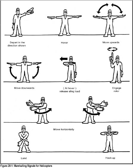
All external loads may be categorized as one of: high density, low density or aerodynamic. The high-density load will be stable while the low density will be decidedly unstable; the aerodynamic load may exhibit both characteristics. You should study the load to determine which description best suits it, and then estimate how it will likely fly.
Whenever possible, position the load so that you can hover the helicopter into wind during the pick-up procedure. This will provide for the most stable hover. If assisted, the marshaller should be positioned in plain view, back to the wind. Usually this will be slightly right of directly in front of the cockpit, about 50 feet away from the helicopter. This position will allow the marshaller to monitor the load as it is lifted off the ground, and to observe a wide area around the helicopter in the interest of safety. It will also make sure that the pilot can see the marshaller. Once in the hover over the load, at the appropriate height, select some easily visible references. Keep these in view as you increase the hover height after hook-up to maintain as vertical a liftoff as possible.
During the hook-up, ground personnel should not position themselves between the load and the helicopter; include this point in your pre-flight briefing. Once the load is attached to the hook, you may commence a slow vertical ascent until the sling becomes taut and the helicopter is centred over the load. Brief the marshaller to position the helicopter directly over the load once you have lifted into the hover. Continue increasing collective while crosschecking the manifold pressure gauge (or torquemeter on turbine engined helicopters) to determine whether sufficient power is available for the transition to forward flight. This portion of the takeoff should be made smoothly to ensure that the load is secure and properly rigged prior to the transition.
Once you are satisfied that all criteria have been met for flight, initiate an altitude over airspeed transition to forward flight. This type of takeoff will ensure that obstacle clearance is achieved rapidly. When at a safe height, allow the airspeed to increase slowly to a speed that will allow the most control over the load. Check for limitations in the flight manual, in any event it is of little advantage to fly faster than 90 mph with any sling load. As the speed increases, pay attention to the flying characteristics of the load and, should oscillations begin, smoothly reduce the airspeed. In this way, you will establish the maximum safe flying speed for your load. Once safely into forward flight, select the cargo hook master switch to “off” (if your helicopter is so equipped).
It is important to reduce the airspeed at the first sign of an oscillation, but do not lower the collective rapidly. All control inputs should be gentle and smooth. Reducing collective (and thereby airspeed) and entering a shallow bank has often proven effective in reducing load oscillations.
If at all possible, plan your approach into wind to preclude the possibility of entering a situation where there is insufficient power available to arrest the descent. An approach angle slightly steeper than normal will ensure that obstacle clearance is provided until the helicopter is over the load release point. Attempt to “fly the load”, observing its speed over the ground, to avoid overshooting the release point. Perform a pre-landing check and set the cargo hook master switch to “on”. Control your rate of descent.
When the helicopter has stabilized over the load, smoothly lower the collective to begin a controlled rate of descent, until the load is on gently placed on the ground. Further lower the collective to create slack in the sling. Depending on the weight of the load, there may be a considerable reduction in collective at this point. Once the sling is slack, release the hook. Before clearing the area, verify that the load has in fact released, and the sling has not hung up, by checking in your mirror or moving a little to one side.
A study of helicopter accidents in Canada will reveal that many are associated with slinging operations. Most are preventable. Plan the slinging you undertake, estimate the flying characteristics of the load, and fly with accuracy and precision. Never let the oscillations of the load reach a magnitude that endangers you and the helicopter; far better to jettison the load than to lose the helicopter. In the event of any emergency in flight jettison the load.
Over the years, you will be asked to sling different loads. In the diagrams below are several ideas, which have worked over the years. Most loads should be comparable to one of the following:
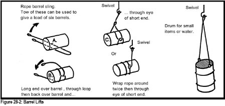
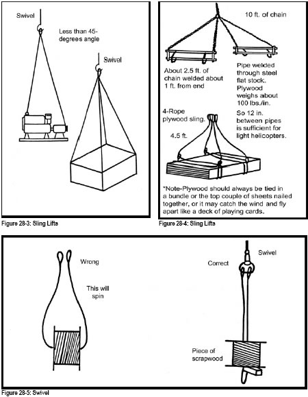
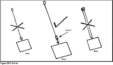
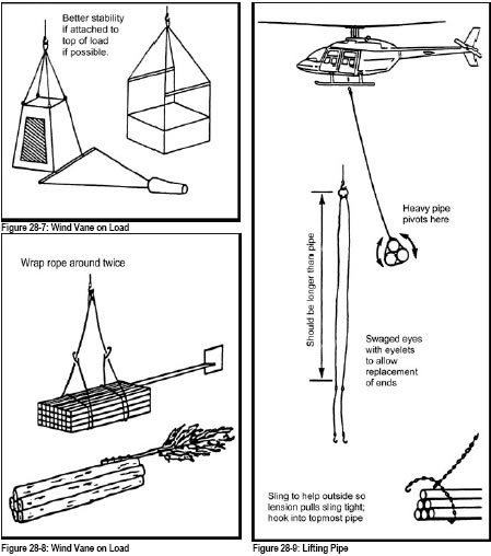
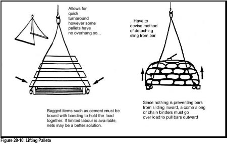
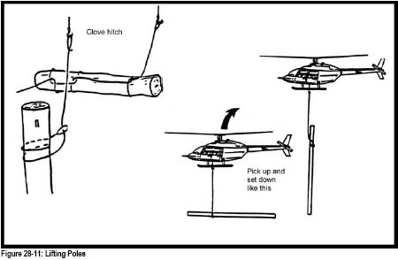
The reasoning behind the type conversion exercise is that there are many types of helicopters; each has different power plants, rotors, flight controls, hydraulic and electrical systems. As a result, the handling characteristics, capabilities and limitations are different for each type.
Helicopter pilots in Canada are required to have their licences endorsed for each type of helicopter they intend to fly. As a helicopter pilot, you may be required to fly several types of helicopter. In this exercise your instructor will teach you the necessary knowledge and in-flight experience to convert you safely and effectively from one type to another.
A thorough conversion is essential to flight safety, particularly when converting from a piston to a turbine-powered helicopter or vice versa.
The majority of the information taught is contained in the flight manual. This is often supplemented by additional training publications. It is essential you have a thorough working knowledge of the different systems and procedures contained in all these publications.
Particular attention should be paid to the limitations section including:
The knowledge acquired will now be applied practically as your instructor commences the flight training necessary for the conversion. The following points will be emphasized:
The time required for a conversion will vary with your experience, skill and helicopter type. Regardless, a successful conversion is dependent on a sound knowledge of the aircraft, and the skill to perform all normal and emergency procedures safely and accurately.
Any situation likely to place a VFR pilot in instrument meteorological conditions (IMC) should be avoided, nevertheless, every year there are instances of pilots accidentally flying into cloud or whiteout conditions. The instrument instruction taught on the private and commercial pilot course does not qualify any pilot to fly IFR. It is designed to assist the pilot who is not IFR qualified, flying a helicopter not suitably equipped, to transition back to visual meteorological conditions (VMC) from inadvertent IMC.
By far the safest and most expedient procedure for a VFR pilot is the time honoured 180 degree turn back to VMC. This procedure is the most appropriate for VFR flights at VFR altitudes, night flights that encounter IMC, or where IMC is a local phenomena, e.g. fog, blowing snow or ice crystals. To achieve the 180 degree turn the pilot must:
Attitude instrument flying is essentially visual flying with the flight instruments substituted for the natural horizon and various reference points around the helicopter. In flight, the instruments provide information concerning:
This exercise description is general in nature as the instrument portion of the course is taught using different methods at different schools. Students should not be overawed by the prospect of instrument flying, as much of it is linked to basic manoeuvres already mastered early in the course, and the majority of the theory is in review of subjects already understood.
The attitude of the helicopter is controlled by movement around its pitch (lateral), roll (longitudinal), and yaw (vertical) axes. The three helicopter flight controls are:
When power is adjusted for airspeed or altitude, the helicopter attitude will be affected, the amount and direction depends on the change made or required. Attitude and bank must be adjusted and yaw eliminated to maintain co-ordinated flight.
The control and performance instruments are grouped as follows:
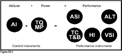
The performance instruments for pitch attitude control reference are:
The performance instruments used for bank control are:
The inherent instability of helicopters requires the pilot to maintain the helicopter in trim as accurately as possible to minimize fatigue and reduce pilot workload. This is achieved by continual cross checking of the instruments using a radial scan. The yaw axis is the unstable in a single rotor helicopter and demands special attention from the pilot.
Performance must change before the performance instruments can react. The pilot must interpret any lag in instrument indications. If the performance instruments indicate that the heading or altitude is not as required, attention is directed to the control instruments while adjusting attitude and power sufficiently to make a correction. The pilot then confirms that the required correction is in progress by referring again to the performance instruments.
While flying with reference to instruments, the pilot continuously extracts information from the performance instruments, and makes control adjustments as required while referring to the control instruments. In extracting this information, the pilot focuses long enough on each instrument to read it. A split second is often long enough to extract the information and then the scan moves on to the next instrument. The attitude indicator is the central instrument. It becomes the hub of the scan so that the pilot’s attention usually returns to it after looking at a particular performance instrument. A diagram depicting the path of the pilot’s viewing pattern would show lines between the attitude indicator to the other instruments, just as spokes radiate from the hub of a wheel. This pattern of viewing the instruments is called a radial scan.
As part of using a radial scan, the pilot frequently scans those instruments that provide the information most needed, given the task at hand. The other instruments are scanned less frequently for backup information. A radial scan that uses particular instruments to get the information necessary to carry out a particular task is called the selective radial scan. For example, when the task is to fly straight and level, the most important performance instruments are the heading indicator and the altimeter. Therefore, the pilot would use the selective radial scan to focus on these two instruments more frequently. As shown in Fig. 30-2, the viewing pattern moves from the attitude indicator to the heading indicator, back to the attitude indicator, and from there to the altimeter.
Of the remaining performance instruments, the airspeed indicator and the vertical speed indicator give information to confirm the attitude; the turn co-ordinator and magnetic compass confirm direction. The selective radial scan uses the same, but less frequent, pattern for these instruments as it used for the altimeter and heading indicator.
To develop the technique of always referring to the right instrument at the right time, the pilot must continually ask the questions:
What information do I need?
What instruments give me the needed information?
Is the information reliable?
Figures 30-2, -3, -4 and -5 show examples of scanning patterns that may be used for specific flight conditions.
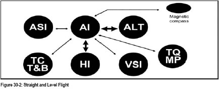
As noted above, Figure 30-2 depicts a selective radial scan pattern for straight and level flight. The answer to the question, What information do I need to fly straight and level?, is information on heading and altitude. The answer to the next question, Which instruments give me the needed information?, is the heading indicator and the altimeter. To answer the question, Is the information reliable?,the pilot must:
In all four diagrams, the heavy arrows depict the scanning pattern the pilot uses most frequently to acquire the needed information. The light arrows indicate a less frequently repeated scan of the supporting instruments. This scan is used to confirm that the main instrument indications are reliable, and also to determine if there is any trend toward an undesired flight condition. The supporting instruments that are more relevant to the task at hand are viewed more frequently than the others. For example, when the pilot is more concerned about altitude control, the VSI would logically be more frequently viewed than the turn and bank indicator.
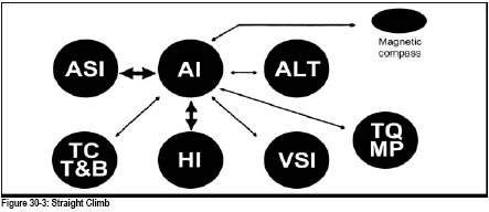
Figure 30-3 shows the correct scanning pattern for the straight climb. The heavy arrows show that the pilot pays most attention to heading and airspeed while climbing. The light arrows depict the important (but less frequent) scan used to confirm heading and attitude information. For the straight climb, the pilot uses the turn and bank and magnetic compass to confirm the heading. The information from the VSI and altimeter confirms that the aircraft is performing as expected in the climb.
By interpreting the information on climb performance and power, the pilot can determine if the attitude indicator is reliable.
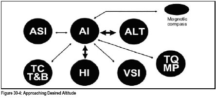
Figure 30-4 shows the most appropriate scan as the helicopter nears the assigned altitude. At this point, airspeed information becomes less important than the altitude information. During the transition from the climb to straight and level flight, the pilot uses the scan pattern that gives more frequent attention to the attitude indicator, with support from the heading indicator and altimeter.
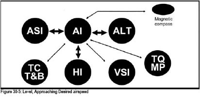
As the cruise attitude is established, the pilot should allow the helicopter to accelerate to cruise speed before setting the cruise power. As shown in Figure 30-5, as the helicopter approaches the cruising attitude, airspeed information becomes more important, and the ASI is again scanned more often, along with the attitude indicator. The pilot also scans the heading indicator and altimeter often to establish and maintain cruise flight.
This consists of flying at a constant altitude (power setting), airspeed and heading (adjusted with cyclic). The rotor disc (miniature aircraft wings) should be level with the horizon on the attitude indicator if the instrument has been adjusted correctly.
When an instrument indicates an adjustment is required to maintain desired performance, the pilot will determine the necessary amount from other instruments. Airspeed, torque/MP, and/or altimeter indicate the adjustment to be made in power or attitude. Corrections to changes in attitude should be made as soon as noticed. Then instead of fixating on that particular instrument to note the effect, the scan is continued to finally return to the original instrument. In this way the entire panel reflects the effect of the adjustment.
Any deviation from the desired heading will be evident from the heading indicator. Immediate and smooth application of cyclic is used to return to the desired heading.
Small attitude and heading excursions when promptly corrected maintain good attitude control. After adjusting, scan the other performance instruments to verify the correction.
During cruise flight, if altitude cannot be maintained with cyclic, without exceeding airspeed changes of plus or minus 10 knots, power is used.
An angle of bank of 15 to 20 degrees should not be exceeded for this exercise. Steep turns will be explained and practised for familiarization purposes.
To enter a turn, the cyclic is eased in the direction required. The initial bank is started with reference to the attitude indicator. When the desired angle of bank is reached, cyclic control pressure is held to maintain the angle of bank, but relaxed somewhat to prevent over bank. Easing the cyclic in the direction opposite to the turn will return the helicopter to straight and level flight. When doing this reference should be made to all available instruments.
Climbing and descending turns use the same technique, but usually the helicopter is established in the climb, or descent, before turning.
Turns to a specified heading should be made in the shortest direction referring to the heading indicator. Since the helicopter will continue to turn as long as the bank is held, roll out must be started before reaching the desired heading. The amount of lead used should be half the angle of bank. The technique is the same as above, except the cyclic is applied on reaching the lead heading.
The rate of 360 degrees in 2 minutes (3 degrees per second) is the standard rate turn. All timed turns are based on these criteria. The position of the sweep hand must be noted, or started, when the turn is initiated. For ease in timing, start the time when the sweep hand passes the 3, 6, 9, or 12 o’clock position. The standard rate of turn is maintained for the predetermined time and then the roll out is started.
Any turn with more than 20° of bank is considered a steep turn. Although they are seldom necessary or advisable in IMC, students will be familiarized with steep turns. This is to ensure they recognize and react quickly and smoothly to large changes in the helicopter’s attitude. The procedures are identical to any other turn manoeuvre, cyclic controlling rate of turn and attitude, collective controlling altitude and airspeed.
To recover from an unusual attitude, the pilot corrects the pitch and bank attitude, adjusts power, and trims the helicopter as necessary. The bank attitude is corrected with reference to the turn and bank indicator, then the ball is centred, the airspeed checked and corrected, then the power if required. Once the helicopter is near to straight and level flight, a thorough scan of all the instruments is then completed and adjustments are made as necessary.
The procedure for recovery from unusual attitudes can be easily remembered by following the order of actions listed below:
NEEDLE
BALL
AIRSPEED
POWER
In this series of exercises you will learn how to fly VFR at night. This does not involve any new flying skills, but there are new sensations and visual cues to which you have to become accustomed. The ideal exercise to accomplish this is the circuit. There is nothing mysterious about flying at night but, because of the lack of outside references, you will rely more on the flight instruments.
In preparation for night flying you should allow time to accustom your eyes to the darkness; it will take approximately 30 minutes for them to adapt in the dark. Try to avoid bright lights during this time.
Circuits are a good introduction to night flying because they cover all of the basic exercises. Night techniques are as follows:
The principles of pilot navigation by night are basically similar to those used by day, except that map reading at night requires some special techniques.
A complete weather briefing and accurate pre-flight planning are even more important than by day. When examining the route, pay particular attention to the elevation of the terrain including any hills, peaks, or other obstructions such as towers. The minimum en-route altitude should be the cruising altitude appropriate to the aircraft track when flying greater than 3000 feet AGL. It is recommended that cruising altitudes be at least 1000 feet above the Maximum Elevation Figure (MEF) for the over flown sectors.
The following points in pilot navigation by night call for special consideration:
Your instructor will select a route for initial pilot navigation practice that includes 3 or more legs with landmarks that are identifiable at night.